ESIM-FWL3 Open Hole Well Logging Simulator
- Preciseness
- Precise mathematical and physical model
- Reliability
- Stable and reliable software and hardware
- Reality
- Highly realistic 3D scene display
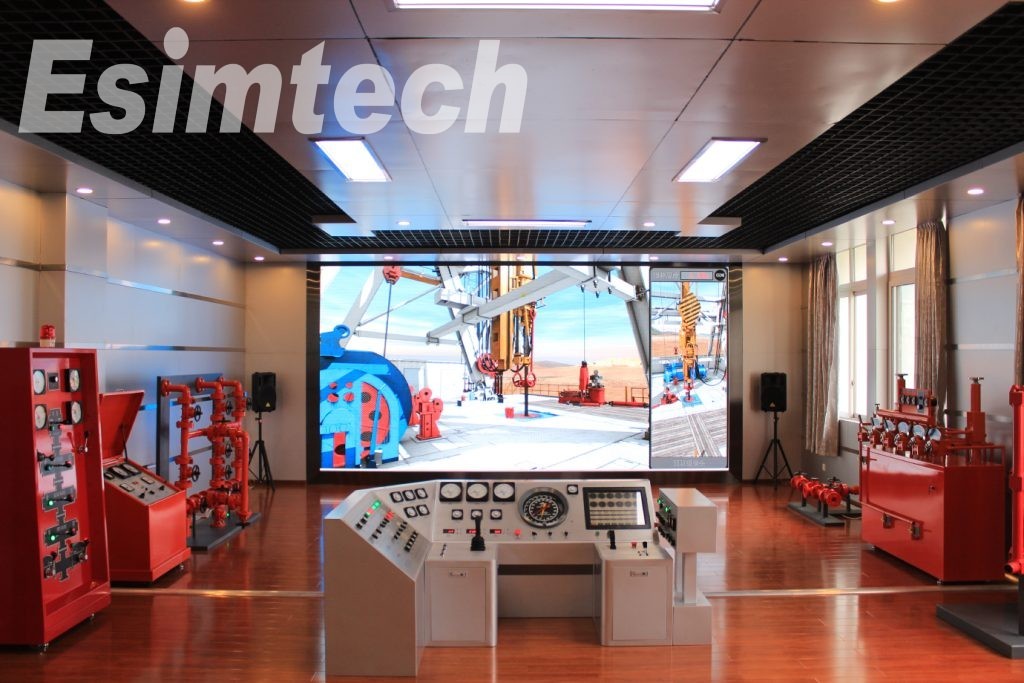
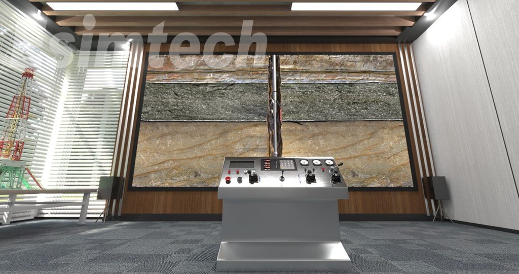
Openhole logging simulation training system has the same operation console and panel as the real equipment. Real-time animation displays the site scene synchronized with the operation, combining with the site noises, makes up an immersive training environment. 3D multi-media animation displays the structure and working principle of logging devices, and the whole process from logging preparation to the end.
1. SystemOverview
1.1 System function
(1) Openhole logging simulation training system has the same operation console and panel as the real equipment. Real time animation displays the site scene synchronized with the operation, combining with the site noises, makes up an immersive training environment.
(2) 3D multi-media animation displays the structure and working principle of logging devices, and the whole process from logging preparation to the end.
(3) The system can complete the training and testing of wellhead operation.
(4) The system can complete the training and testing of drawworks raising, lowering, raising and lowering with stuck operation.
(5) The system can complete the training and testing of logging software operation.
(6) The system can complete the training and testing of technician theory training.
(7) The system uses strict mathematical models to realize simulation calculation, and displays important parameters changing trend in the form of plots.
(8) The system can give score to students’operation automatically. Auto score system in the equipment can give out the scores according to students’operation procedure and operation skill, and also give out the point-deduction points.
(9) Through online examination, the system can complete the examining of theory knowledge and give out score automatically
1.2 Training items
1.2.1 Wellhead worker
-
Wellhead equipment installation
-
Bridle making
-
Connecting logging tool (Connecting logging cable)
-
Cut-threak freeing and fishing
-
Equipment dismantling
1.2.2 Winchman
-
Raising normally
-
Lowering normally
-
Lowering and sticking
Raising and sticking
1.2.3 Surface unit operator
1
-
Spontaneous potential logging
-
Conventional resistivity logging
-
Lateral logging
-
Microresistivity logging
-
Induced well-logging
6. Acoustic logging
7. Gamma-ray logging
8. Density logging
9. Neutron logging
10. Openhole diameter logging
1.2.4 Animation
-
Spontaneous potential logging
-
Conventional resistivity logging
-
Lateral logging
-
Microresistivity logging
-
Induced well-logging
-
Acoustic logging
-
Gamma-ray logging
-
Density logging
-
Neutron logging
-
Openhole diameter logging
-
Introduction to basic logging material
Maintenance of logging wellhead equipment
Technology of openhole logging and horizontal well logging
Technology of cable perforation
Technology of tubing conveyed perforation
Working principle and maintenance of basic downhole logging tools
Basic operation and maintenance of surface unit
Making and maintenance of bridle
1.2.5 Sub-systemof examination
This system is a general on-line examination system based onB/Sframework. It can bu used for INTERNET and local area network online examination. The system can complete examination for more than one persons at the same time, and only requires normal configured server, no need to do any any setup at client side.
This system is a general on-line examination system based on B/S framework.It can bu used for INTERNET and local area network online examination.The system can complete examination for more than one persons at the same time,and only requires normal configured server,no need to do any any setup at client side.
The system contains the following functions:
-
User can set examination mode as required;
-
There are a lot of professional questions in the system database. Meanwhile, user can customize the questions type according to examination need.
-
The question input function is similar as Microsoft office word;
-
The system can give out scores automatically for all question types, and can monitor the exam at the same time.
-
The system has classification management and remote management capabilities;
-
The system has flexible user setup function.
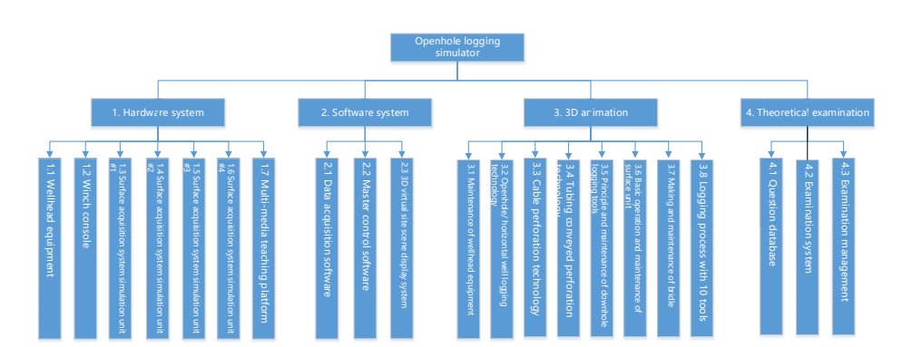
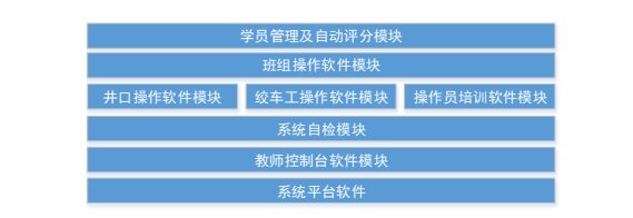
1.3 System function structure
Openhole logging simulation training system can be divided into four parts:hardware system,simulation training software system,animation and sub-system of theoretical examination.The structure is as shown in the following figure:
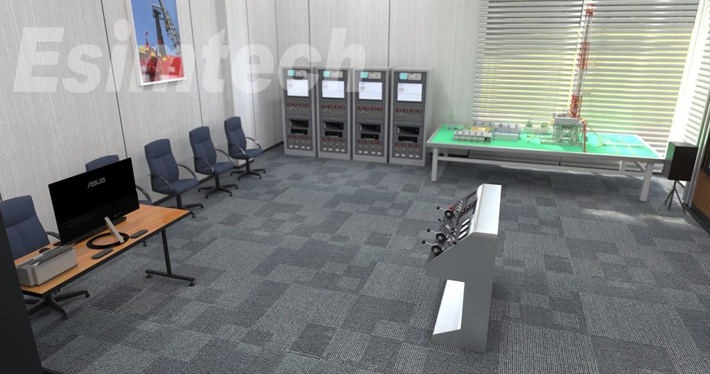
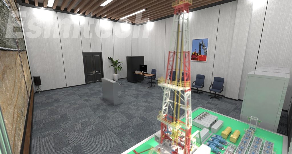
2. HardwareSystem
2.1 Openhole wellhead device
2.1.1 Components and specification
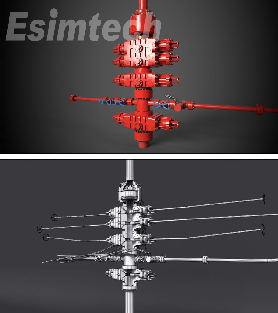
Openhole wellhead device is made according to real wellhead device. The device is made of metal, with the height of 1.8m. The substructure is made of wood, in order to present the platform better. This model is made short, and only shows the part below derrick monkey board.
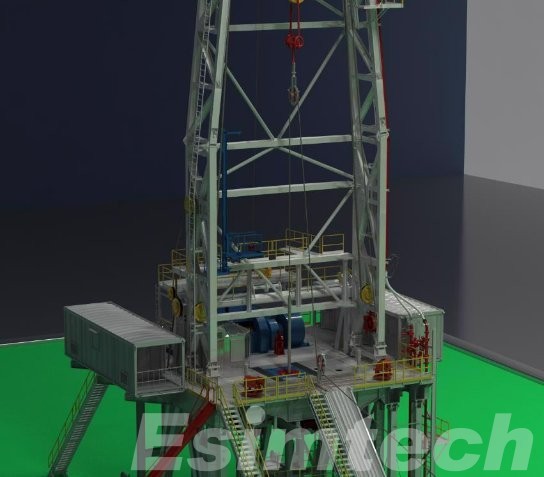
Figure 3-2 Openhole wellhead devices
2.1.2 Openhole wellhead device usage
1) Used to present the placing and position of onsite logging units.
2) Used to present the placing and installation of surface units.
3) Used to present the installation position and connection of top sheave and lower sheave when logging.
4) Used to present the connection of logging site units.
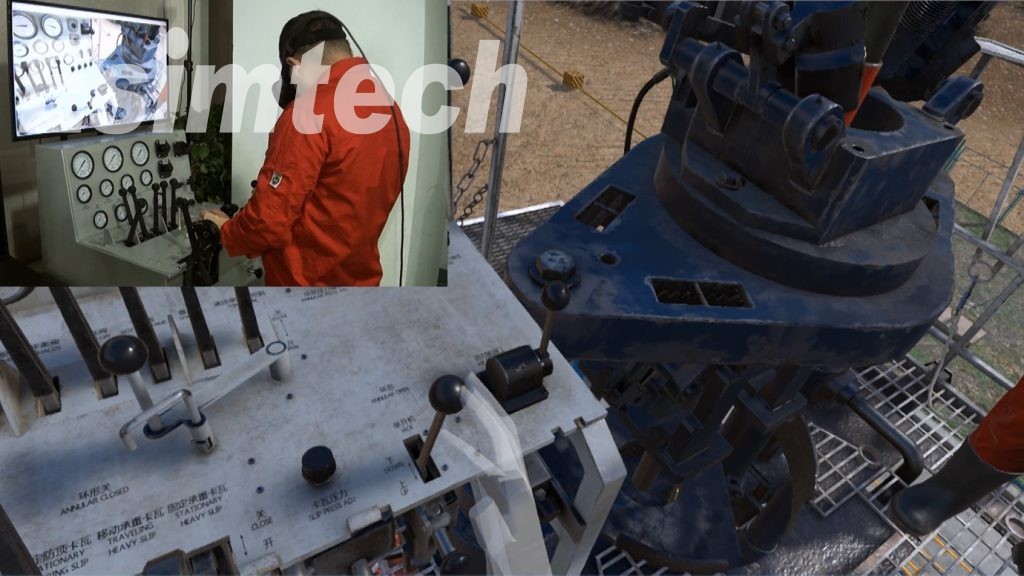
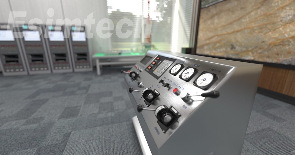
2.2 Drawworks console
2.2.1 Components and specification
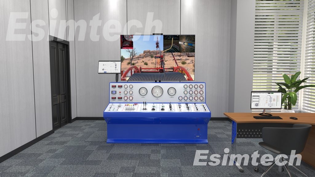
Drawworks console is designed according to Oehman’s drawworks (Eclips-5700 series of Baker Hughes). It is of all metal structure, with cold rolling sheet of 1.5mm thick. The frame is all steel, with aluminum panel. The surface is processed as acid pickling, phosphating, and electrostatic spraying, which is beautiful and durable. The functions and operation method of drawworks panel and the control valves are the same as real drawworks. The main controls on the panel include: drum control lever, throttle control lever, brake control lever, system pressure regulator, emergency cut-off, hydraulic motor speed shift switch, gear switch, engine meters group, oil supply pressure meter and system pressure meter, etc.
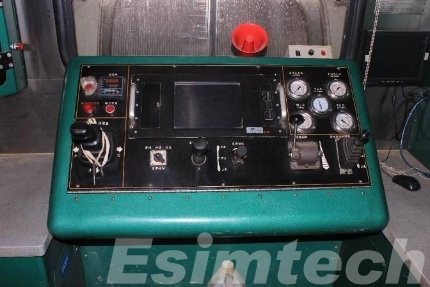
Figure 3-3 Drawworks console onsite
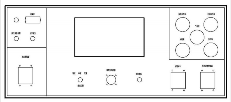
Figure 3-4 Simulated drawworks console panel
1) Emergency unloading
Used to control hydraulic system. When the knob is turned at “OFF”position, the drum stops running. When the knob is turned at “ON position, the drum runs normally. When the device stucks, drawworks worker start emergency cut-off valve, then the drum will stop immediately.
2) Press to spray oil
Press the switch. The spayer spay oil to cables. This motion is displays by 3D animation.
3) Hydraulic cable racker
When the lever moves side by side, Martin-decker lifting arm moves with it, to guide the cable to wind neatly. Martin-decker lifting arm and drum cable are displayed by 3D animation.
4) Speed control
Drum speed control has 3 gears: high, middle and low, used to control the speed of drum rotation.
5) Drum direction control
When drum direction control is at middle position, drum stops. Pull drum direction control upwards, the cable lowers. The more the control is pulled, the faster the cable is lowered. Pull the control downwards, the cable raised. The more the control is pulled, the faster the cable is raised
6) System pressure regulator
This is used to set the tension of hydraulic system. Turn the handwheel clockwise, the system tension increases. Turn it counter-clockwise, the system tension decreases. When the cable tension reaches the set tension value, the drum stops. When the device stucks, pressure regulator reaches the set tension, the drum stops rotation, to protect the cable.
7) Drum brake
Pull the brake lever downwards, the braking force increases, till brake completely.
8) Backup drum control
The function of the backup drum control is the same as drum direction control.
9) Oil temperature meter, used to display oil temperature of hydraulic system;
10) System pressure meter, used to display system pressure. When cable tension increases, system pressure increases. The system pressure is not to exceed 25 MPa.
11) Oil supply pressure meter, used to display oil supply pressure.
12) Air pressure meter, used to display air pressure.
13) Auxiliary pressure meter, used to display auxiliary pressure.
14) Negative pressure meter, used to display negative pressure of hydraulic system.
15) Drawworks panel, including depth indication, speed indication, tension indication, stuck indication, and other controls. Depth indication shows the depth of cable into well. Speed indication shows the cable moving speed. Tension indication shows the tension of the cable.
2.2.2 Drawworks console usage
-
Used to simulate logging device tripping in and out control and system tension control, to cultivate the ability of control drawworks.
-
Used to simulate judging and treating of testing device stuck, to cultivate the ability of handling devices stuck downhole.
-
Used to simulate judging and treating of logging accidents, to cultivate the ability of handling logging accidents.
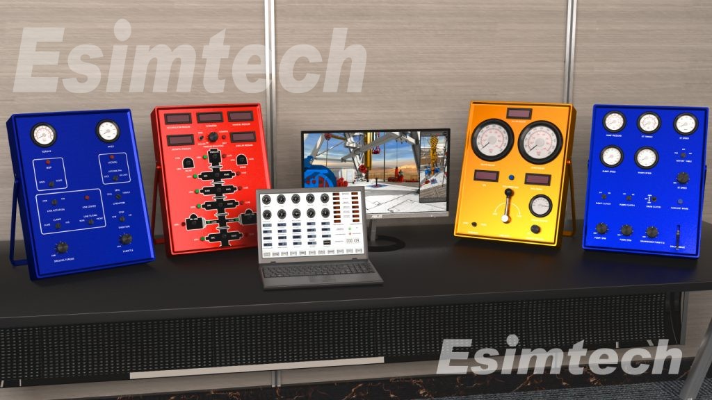
2.3 Logging ground acquisition system simulation device
2.3.1 Components and specification
Logging ground acquisition system simulation device is designed according to Eclips5700 series ground acquisition system from Baker Hughes, integrated with other common functions of ground acquisition system. It is of all metal structure, with cold rolling sheet of 1.5~2.0mm thick. The frame is all steel cabine combination design. The surface is processed as acid pickling, phosphating, and electrostatic spraying, which is beautiful and durable. It can also be customized according to clients’room size. The components contain: oscilloscope, monitor, signal acquisition and processing panel, AC/DC power supply, keyboard, industrial control computer, thermal plotter, power supply, etc. Each component is as shown in the following figure.
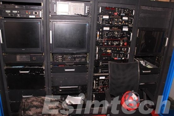
Figure 3-5 Logging ground acquisition system panel layout
-
Oscilloscope
-
Monitor
-
Computers, used to run simulation device software. The original logging data in the software come from actual logging file.
-
Thermal plotter completes the printing of graphs and logging curves, supporting successive printing. Resolution is above 300*300 dpi.
-
AC, DC power panel
-
Signal acquisition processing panel/ Composite control box
2.3.2 Usage of logging ground acquisition system simulation device
-
Used to simulate the panel and testing software function of real ground operation system. Logging ground acquisition system simulation device acquires the simulation signal of downhole device, completes the functions of processing, displaying, recording and printing simulation testing signal, and receiving the control signal sending by data base, operation information, parameter information, etc.
-
Used to simulate logging methods, technology process, generation of logging device signal and logging curves, and preliminary judgement of logging quality.
-
Used to assess students’ skills of device connection, using of logging software and handling of logging accidents.
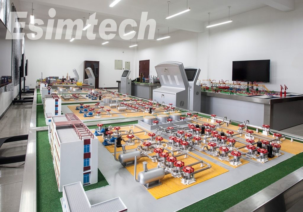
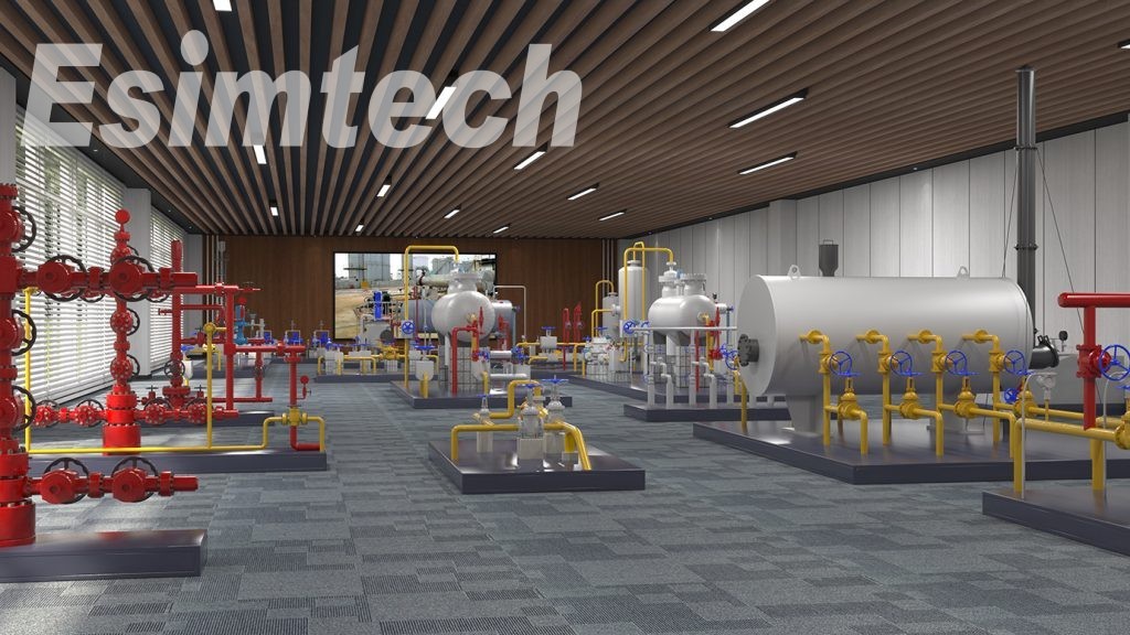
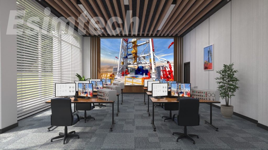
2.5 Multi-media simulation teaching platform
2.4.1 Components and specification
-
Active loudsperker
|
LEXO-101 Loudspeaker |
|
|
Brand/ Model |
LEXO-101 |
|
Frequency range |
50Hz~20KHz±3dB(HZ) |
|
Cover range |
90×60 |
|
Canning material |
Laminated plank |
|
Size |
422×664×440mm(cm) |
|
Voltage |
AC220V/50Hz(V) |
-
Projector: Pansonic FD605 professional industrial projector
|
Pansonic FD605 projector specification |
||
|
Optical parameters |
Product type |
Industrial projector |
|
Projection technology |
DLP |
|
|
Video chipset |
Single DLP digital chip |
|
|
|
Projector feature |
Interactive |
|
Brightness |
6500 Lumens |
|
|
Brightness mean |
90% |
|
|
Contrast ratio |
2000:1 |
|
|
Standard resolution |
XGA(1024*768) |
|
|
Light source |
Super-high pressure mercury lamp |
|
|
Lamp q’ty |
2 |
|
|
Lamp power |
300W |
|
|
Environment parameters |
Working temperature |
0-45℃ |
|
Working humidity |
20-80%(non-condensing) |
-
150 inch electric remote control metal curtain
|
OHYES 150 inch curtain parameters |
|
|
Brand |
OHYES |
|
Model |
150 inch 16:9 |
|
Material |
Metal |
|
Type |
Electric curtain |
|
Type |
Hanging curtain |
|
Size |
150 inch |
|
Ratio |
16 : 9 |
-
Video frequency divider and video cable: Adopts four-port video frequency divider and accessory high quality non-destructive digital video cable. Can output four non-destructive digital video signal at the same time.
-
Instructor station and accessories: Used to place graphics computer and data acquisition computer.
2.5 Master control computer
Master control computer communicates with PLC module by serial interface. This computer is the core of the whole system. All hardware data, operation data gathered here. Through the control logic of the master control software in this computer, students’ operation can be monitored at real time. Lenovo business computer is used in the system. The main parameters are as in the following table:
|
Main parameters of data acquisition computer |
|
|
CPU |
I7 |
|
Memory |
16G |
|
Hard disk |
240G |
|
Serial port |
1 native serial port |
|
Monitor |
22 inch 16:10 liquid-crystal display monitor |
2.6 3D graphic computer
3D graphic computer receives the command of master control computer, displays the working condition of well logging site, calculates the position, parameters and working condition of various devices on site, and sending the graphic to projector. The main parameters of graphic computer are as in the following table:
|
Main parameters of graphic computer |
|
|
CPU |
I7-9700K or equivalent |
|
Memory |
16G |
|
Hard disk |
1t |
|
Serial port |
RTX2070 Super 8G or equivalent |
|
Monitor |
22 inch 16:10 liquid-crystal display monitor |
2.7 Typical installation effect picture
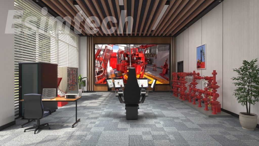
A typical installation effect picture is as shown in the following figure. Openhole wellhead device is placed on the left side. Drawworks console and projector are placed in the middle. And logging surface units are placed on the right side.
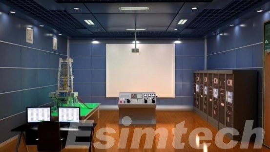
Figure 3-10 Layout diagrammatic drawing
3. SoftwareSystem
3.1 Overview
Openhole well-logging simulation training system contains 4 sets of softwares: main control software, graphic software, examination sub-system software, and surface acquisition software.Master control software and graphic software fulfill simulation training while examination sub-system completes theory testing function.
3.1.1 Software system function description
System software function
(1)Function of training sub-system: providing theory and operation training to serviceman, winch man and operator. Theory training provides test questions, multimedia instruction films, and animations, allowing trainees to understand device components, working principles, operating procedures and incident prediction as well as treatments. Operation training combining with 3D graphics, voice and system prompts fulfills various specific trainings.
(2)Function of question bank: add, delete, modify, generate test paper and mark tests.
(3)Historical logging data function: manage historical logging data, and provide primary data for training and tests.
(4)Data acquisition function: collect and send multiple signals such as state of simulation machine and analogue quantity as well as signals in and out of wellhead and drawworks.
(5)Trainee management function: add, delete, modify and print trainee’s basic information.
(6)System diagnosis function: collection all device’s operable state to estimate whether devices are operating well. Devices are to be corrected or calibrated if not.
(7)Auto scoring and printing function: give score to trainee’s operation according to specific requirements; reasons are given why points are deducted and printing option is accessible
(8)Operation procedure control
Decide whether trainee’s operation is correct as per logging operation procedure for moving to next step. System response time less than 0.5s. There are logging operations by 10 logging instruments: self-potential logging, conventional resistivity logging, lateral logging, micro-resistivity logging, induced well logging, acoustic logging, natural gamma-ray logging, density logging, neutron logging and openhole diameter logging.
(9)Data recovery: restore logging historical data back to raw data, and feed back to all devices. Set and adjust parameter which varies and reflects on simulator.
(10)Curve plotting and printing function: plot curves according to simulated restored data and transmit to thermal plotter.
(11)Malfunction presetting and treatment: malfunction presetting is allowable in the examination system. For example, tool stuck could be set at any depth which requires trainee to resolve. System evaluates based on the results incurred from trainee’s operation.
(12)Data modelling: build mathematical and physical model and calculate device’s current state according to parameters; send data to graphic computer to show plotted downhole 3D animation.
3.2 Software structure
Main control software contains several software modules: platform software, instructor console software, wellhead operation software, winchman operation software, operator training software, team operation software, system self-diagnosis software, trainee management, and automatic scoring software. The relationship among those modules is shown as the following figure:
3.2.1. Instructor console software module
This module employs the following functions:
-
Serial communication: Receive PLC collected hardware data which is filtered and converted to required data.
-
Network communication:communicate with graphic computer,share hardware data,send and receive graphic command.
3.2.2. Wellhead operation software module
This module employs the following functions:
-
Calculate wellhead hydraulics parameters in real time according to mathematical model and student’s operation.
-
Transmit parameters to wellhead instrumentation.
-
Judgement of wellhead operation: judge if wellhead operation by student is correct and give tips on incorrect operation.
-
Make synchronous display between graphic computer and wellhead.
3.2.3 Winchman operation software module
This module has following functions:
-
Calculate drawworks lowering and raising speed according to drawworks operational data and the type of downhole instrument.
-
Transmit parameters to instruments on the drawworks console.
-
Judgement of drawworks operation: judge if drawworks operation by student is correct and give tips on incorrect operations such as lowering and raising of winch and zero setting, etc
-
Make synchronous display between graphic computer and drawworks operation.
-
Control the status of displaying instruments of graphic computer in down hole.
-
Setdownhole scenarios like tool being stuck.
3.2.4 Operator training software module
This module contains the following functions:
-
Receive student’s operational data sent from surface acquisition system analogue machine.
-
Record operator’s operational details from surface acquisition system.
-
Send simulation depth of drawworks to surface acquisition system analogue machine.
3.2.5 Team operation software module
This module integrates following functions:
-
Collect data from wellhead, drawworks and surface acquisition system.
-
Calculate parameters during entire logging process by employing impeccable mathematic model
-
Setting of tool string:setup surface tool string, and display weight, length and depth of tool string.
-
Team training setting:
-
Operational information display
1) Openhole information display: display pre-set openhole information in team training and assessment.
2) Stratum information display: display information of the stratum currently set like valid depth of oil layer, porosity, hydrocarbon saturability, permeability and etc.
3) Malfunction setting: instructor couldsetdrawworks stuck scenario
1) Information display of drawworks operation: display various element status and parameters on the drawworks console such as tension, depth, speed, etc.
2) Operational information display of surface unit: display various element status and operating information from surface unit.
3) Information display of downhole tools: display operating conditions of downhole tools.
4) Operator information: display operator’s information logged in.
3.2.6 System self-diagnosis module
This module contains the following functions:
-
Detect whether devices on wellhead, drawworks console and surface acquisition system are correct, and issues a list to be repaired if not.
-
Set deviation value, status value, min/max controlling value and temperature deviation value from liner continuous data acquisition equipment.
3.3 Surface acquisition system software
Surface acquisition system software is running on 4 simulation surface acquisition systems, including system platform software, system self-diagnosis module, student console software and operator training software.
3.3.1 System self-diagnosis module
This module has the following functions:
-
Detect whether devices on wellhead, drawworks console and surface acquisition system are correct, and issues a list to be repaired if not.
-
Setdeviation value, status value, min/max controlling value and temperature deviation value of liner continuous data acquisition equipment.
3.3.2 Student console software moduleThis module has the following functions:
This module has the following functions:
-
Set training mode which allows student to enter system for practice without entering trainee information.
-
Set examination mode which requires instructor to confirm on practical operation examination after student information being entered
-
Both Individual and team training & examination are accessible.
3.3.3 Operator training software module
Being the core module of surface acquisition software system, it is designed strictly as per Baker Hughes’ eclips-5700 logging system. It has the following functions:
-
Malfunction can besetat multiple points.
-
Downhole tool string assembly: Tool string assembly is flexibly chosen according to the logging tasksetby central control computer.
-
Downhole tool scaling: conduct scaling operation in down hole such as well diameter scaling and induction scaling.
-
Logging simulation
1) Initializing acquisition system
⚫ Choose which CPU as the display processor and as the acquisition processor in OCT selection window.
⚫ Choose one OTC from OTC selection window.
⚫ Load main scale and main calibration data.
⚫ Setprocessing parameter.
2) Before-logging verification, conduct necessary before-logging verification on downhole tools.
3) Tools to downhole
⚫ Tool string zero-setting
⚫ Conduct before-logging verification while some tools to be verified before logging in down hole.
⚫ Choose logging direction and recording mode.
⚫ Record data.
4) Determination of total depth
⚫ Calibration of cable depth.
⚫ Reset calibration depth.
5) Raising logging
⚫ Change parameters.
⚫ ACTS Open required ACTS.
⚫ Record repetitive curves.
⚫ Record main curve.
⚫ Conduct calibration on downhole tools after logging.
6) Data save
7) Data playback
5. Record student’s every step on the simulation software and send to master control computer.
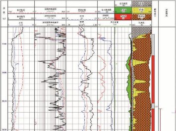
Figure 4-3 Logging plot generated from simulated downhole data
3.3.4 Software development tools for surface acquisition system
Microsoft Visual Studio 2010, the most popular application tool on windows, is employed as the program development environment. C#, mature, efficient and universal, is an object-oriented programming language, widely applied in software development field.
3.4 Graphic computer software
3.4.1 Display software for virtual 3D scenes
According to requirements of technological process, display software for virtual 3D scene combined with logging items demonstrates operational processes in training mode and examination mode, and render operation effect with 3D animation at real time. It has the following functions:
-
Virtual 3D scene display software is automatically started the moment the instructor activates one-button start.
-
Start initialization of scenes, tools, surface and downhole status based on selected technological process.
-
Plot relevant graphics and 3D real-time animation based on student’s operation after receiving instructor’s command.
-
Setup 3D camera visual angle according to technological process and operator’s type of work. Training staff includes wellhead service man, winchman and operator. This software adjusts suitable viewing angle accordingly just like feeling at real logging site
-
Display downhole view of downhole tools and formation sectional view according to involved downhole tools. Display equipment’s internal structure & working condition as well as downhole mud circulation at real time.
-
Control playing 3D animation according to operation procedure and function setting.
-
Synchronize movement of virtual equipment with trainee’s operation, available to observe the working status of all wellsite equipment.
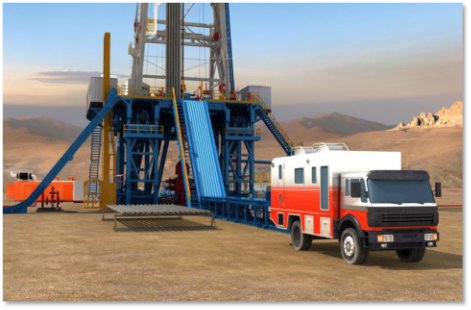
Figure 4-5 Logging image from virtual 3D scene display software
3.4.2 Typical interface
1. Display logging truck entering images in panoramic view when logging starts, including wellsite environment showing, logging truck parking procedure and logging preparations
Figure 4-6 Logging site image
2. Display wellhead view interfaces when tools at wellhead.
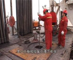
Figure 4-7 Logging wellhead image
3. Display wellsite views from winch man’s perspective.
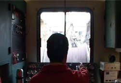
Figure 4-8 Drawworks image
4. Show real-time wellhead views and downhole views when tools are in down hole.
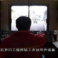
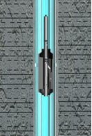
Figure 4-9 Downhole display image
System Features
Strict mathematical models, complying with real technical demands
Automatic scoring function, giving out scores and point-deduction points.
3D multi-media animation, displaying the whole logging process
Online examination, completing theory knowledge test and giving out score automatically
Components
Openhole wellhead devices
Q&A
- Do you have any happy clients or testimonials about your simulator?
“Creating value for customers”, which is always emphasized in our company. With this original intention, Esimtech Company develops simulators with high quality, and provide timely and enthusiastic services. For all these years, the products and services provided by Esimtech are highly praised by our customers.
- Can you do custom work for my specific rig, company, or field?
Esimtech provides customization service, which is the biggest feature of the company. Esimtech has a strong production team skilled in programming and animation production. Both hardware and software can be customized to comply with the real situation.
If you have any needs or questions about the drilling simulator, please feel free to contact us.