ESIM-FOR3 Oil Recovery Simulator
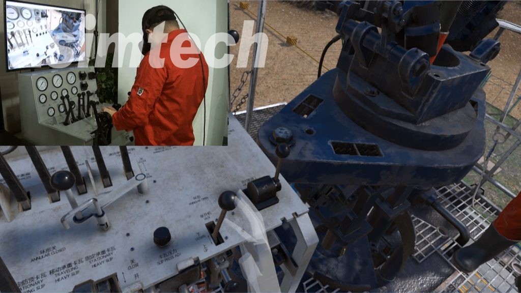
- Figure out the working status, manifold pressure and so on at real time during student’s operation.
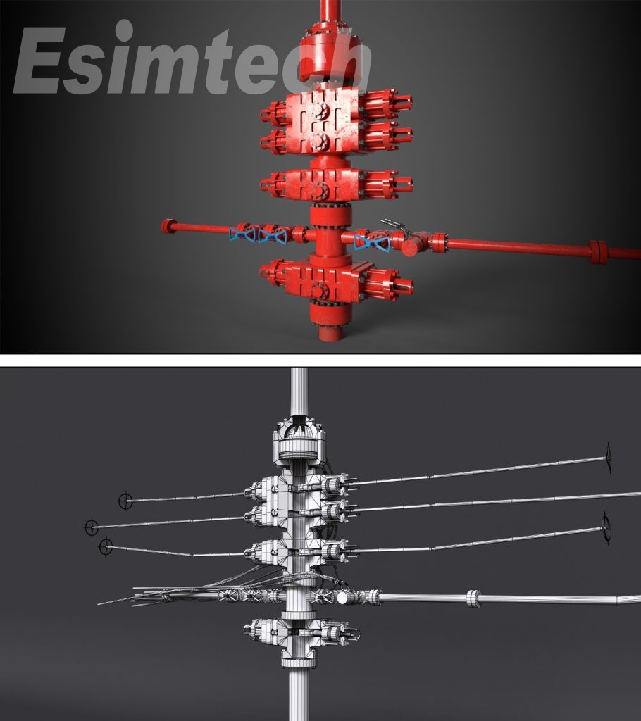
- Present underground scene, device motion and device working theories,
- Accident setting function enables students to judge the cause of problems and master the way of handling common problems.
- Oil well parameter are adjustable, including pressure, temperature, flow rate, etc.
- The function of the system is expandable.
1. Introduction
ESIM-FOR3 The oil recovery simulation training system is developed by Southwest Petroleum University and Chengdu Esimtech Petroleum Equipment Simulation Technology Exploitation Co,Ltd.It is an advanced training system with complete functions,satisfying the requirement of oilfield training.
The oil recovery simulation training system is the combination of technologies of petroleum engineering,oil and gas storage and transportation,computer technology and virtual reality technology.It enables students to understand the inner structure and working theories of oil recovery devices,and the typical stations and process.It can provide training for primary workers,intermediate workers,senior workers,technicians,senior technicians,etc.The training provided by this system make the students master theories of various oil recovery devices and usage,as well as the method of treating common accidents.
The system adopts“flow coupling”to calculate the pressure,flow rate,temperature in the pipe.Advanced mathematical model makes the training more immersive.Common accidents and device fault can be set at anytime by the instructor with the use of accident preset technology.The displaying system with large size screen presents the whole process clearly,which make the training more effective by saving time and strengthening the students’understanding.
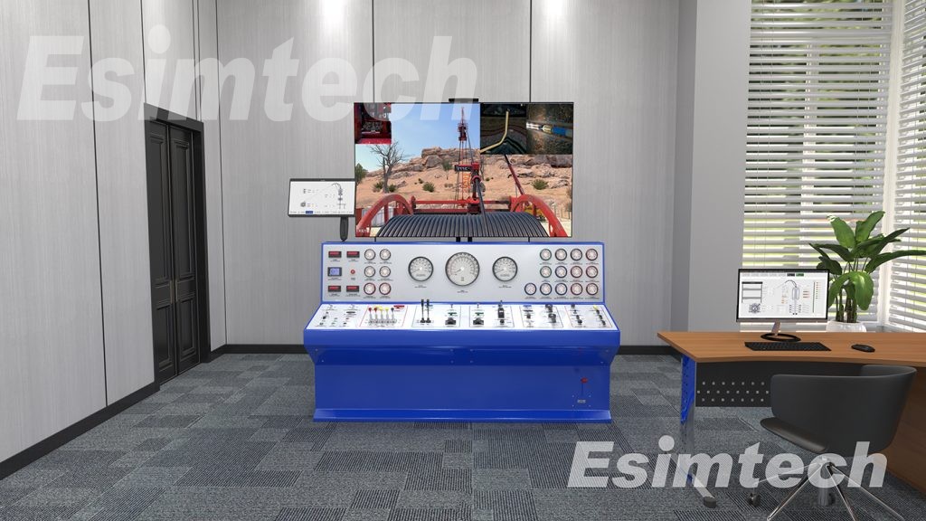
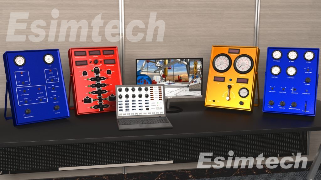
This system consists of oil production simulation platform,graphics system and other accessory software.The consoles of this system are the same as the real equipment.The pipes are made by metal which are sturdy and durable.The panels,operations and parameter displaying are also the same as the real equipment.Hardware system is designed according to industrial standard.Data acquisition and control system adopts PLC which ensures the reliability of the system.This system has low input and maintenance input.There is no real liquid within the device,and all data acquisition is completed by sensors,so there is no security risk of high pressure and poisonous materials.
2. SystemComponent
2.1 Major Hardware
Hardware system layout is as shown in figure 1.
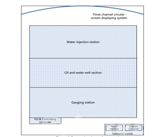
Figure 1 System hardware framework
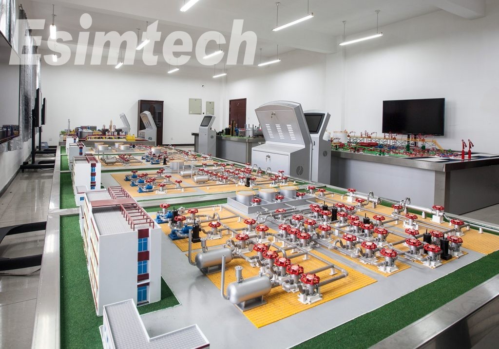
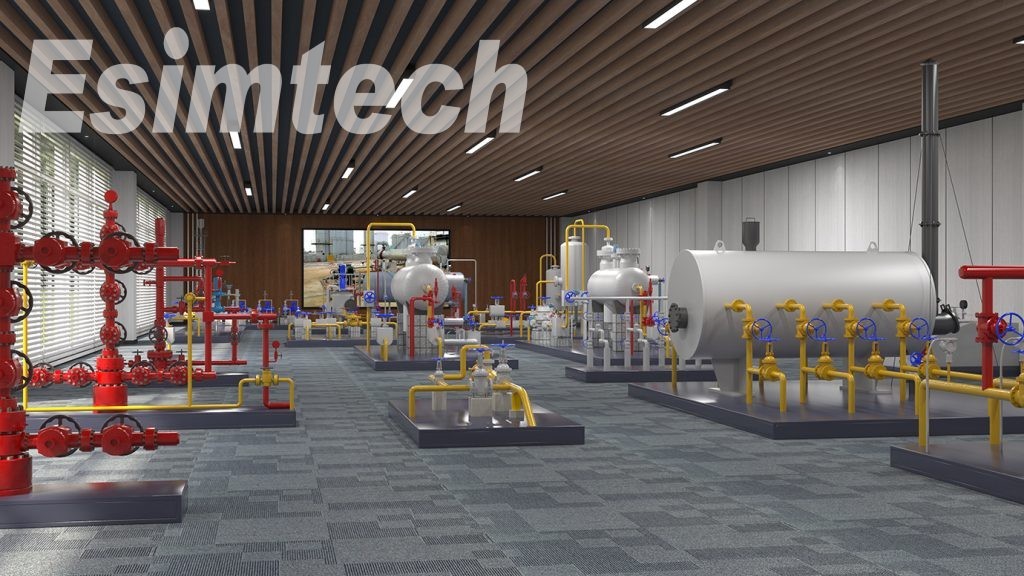
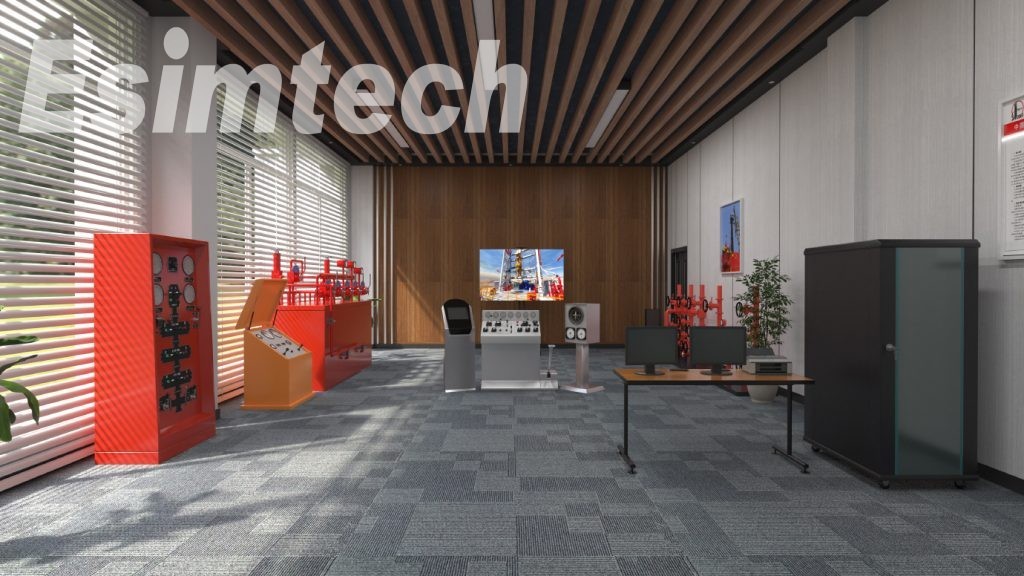
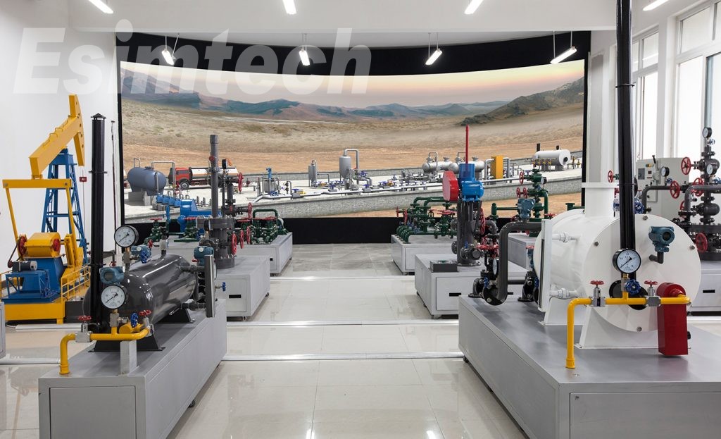
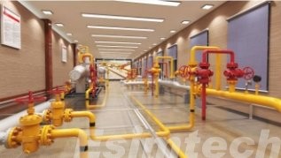
Oil recovery simulation training system is composed of oil well simulation platform, gauging room simulation platform, and water allocating simulation platform. Figure 2 shows the various part of oil well section. The upper section is three different types of wellheads, including rod-pumped well teaching platform, screw pump well teaching platform, and electric submersible pump teaching platform. The three wells are connected to the gauging room platform.
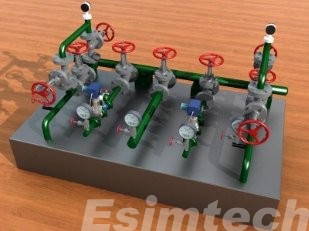
Gauging room platform contains gauging station, joint station and oil storage tank. Water allocating simulation platform includes a process of water injection, a water injection well, devices that injecting water to several water injection well, a plunger pump, a water pump and a set of water storage tanks, as shown in figure 2.
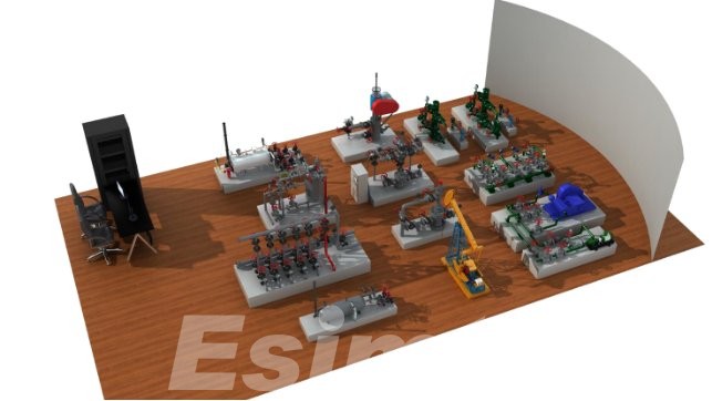
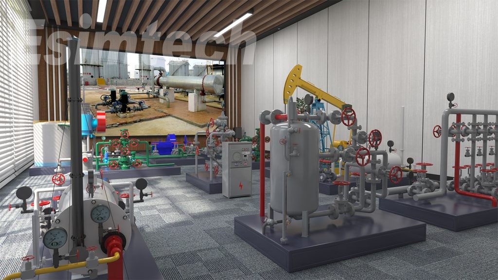
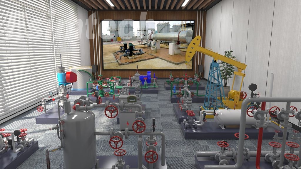
Figure 2 Typical system devices layout
The oil recovery simulation training system is mainly composed of pumping unit training platform, ESP well training platform, screw pump wellhead training platform, metering plant simulation platform and water allocating simulation platform. There are various modules in each platform, such as pumping unit wellhead module, pumping unit module, furnace module, etc. All the modules adopt the metal structure and designed by scale according to the dimension of the real devices. The valves in the modules are modified based on the real valves, with sensors inside. The operation is the same as on the real site. The meters in the modules are also modified, and controlled by the master control computer at real time. The readings of the meters are synchronized with the students’ operation.
The detailed configuration is as follows:
Pumping unit teaching platform
|
|
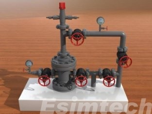
Pumping well wellhead The pipes are made of metal,with actual valves,inside the pipes there are sensors.All valves are operable.Pressure meter is analogue meter.This device is designed according to the size of real equipment;it can also be customized according to different region and technology. |
|
|
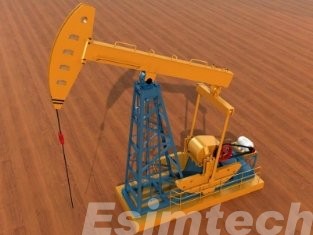
Pumping unit It is designed according to the appearance of standard pumping unit.It can simulate the working condition of pumping unit when opening and shutting in.This device is designed according to the size of real equipment;it can also be customized according to different region and technology. |
|
|
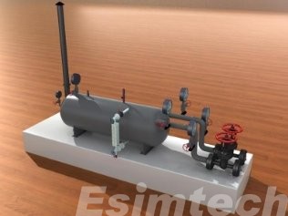
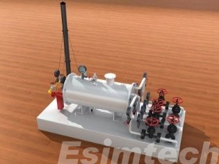
Single well furnace Single well furnace is adopted at wellhead with single incoming and outgoing line,and bypass valves.It is made of metal.All valves are actual and operable,with sensors inside.Pressure meter is analogue meter,and can send operation to controlling computer at real time.There is PLC inside the base structure.This device is designed according to the size of real equipment;it can also be customized according to different region and technology. |
2. Electrical submersible pump well teaching platform
|
|
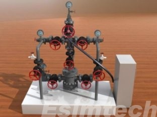
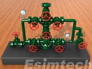
Electrical submersible pump well wellhead Double wing production electrical submersible pump well, is made of metal, with sampling valves. All valves are actual and operable, with sensors inside. This device is designed according to the size of real equipment; it can also be customized according to different region and technology. |
|
|
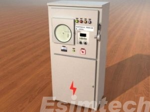
Electrical submersible pump controlling cabinet It is made the same size as the real equipment, simulating various accidents, such as phase failure, air lock, pump too large/ small, sand sticking, etc. |
Screw pump wellhead training platform
|
|
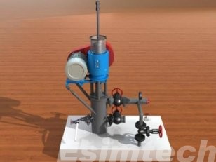
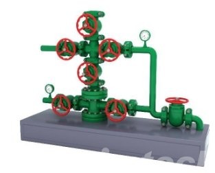
Screw pump well wellhead The motor can run.This device is designed according to the size of real equipment;it can also be customized according to different region and technology. |
4. Metering plant process simulation platform
|
|
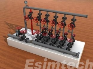
Incoming manifold This manifold adopts dual paths structure.One path leads to furnace,the other leads to gauging separator.This device is designed according to the size of real equipment;it can also be customized according to different region and technology. |
|
|
Water jacket furnace This device adopts dual incoming and dual outgoing structure, made of metal and by scale. This device is designed according to the size of real equipment; it can also be customized according to different region and technology. |
|
|
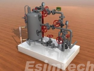
Gauging separator Vertical gauging separator, with bypass and bleed off pipes, is made of metal. This device is designed according to the size of real equipment; it can also be customized according to different region and technology. |
|
|
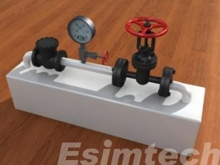
Outgoing pipeline This device is composed of one-way valve, pressure meter and outgoing main valve. |
5. Water allocating station process platform
|
|
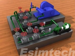
Water injection station This station is composed of a plunger pump,a water feeding pump,pipes and valves.This device is designed according to the size of real equipment;it can also be customized according to different region and technology. |
|
|
Water allocating station This station is composed of four sets of water allocating valves. |
|
|
Water injection well#1 he pipes are made of metal,with actual valves,inside the pipes there are sensors.All valves are operable.Pressure meter is analogue meter.This device is designed according to the size of real equipment;it can also be customized according to different region and technology. |
|
|
Water injection well#2 The pipes are made of metal,with actual valves,inside the pipes there are sensors.All valves are operable.Pressure meter is analogue meter.This device is designed according to the size of real equipment;it can also be customized according to different region and technology. |
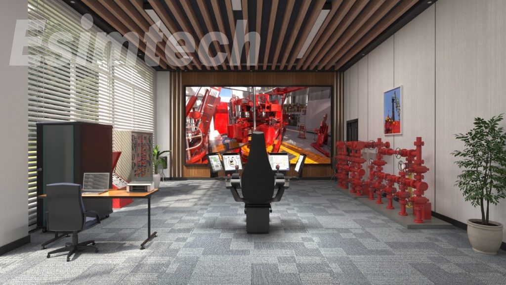
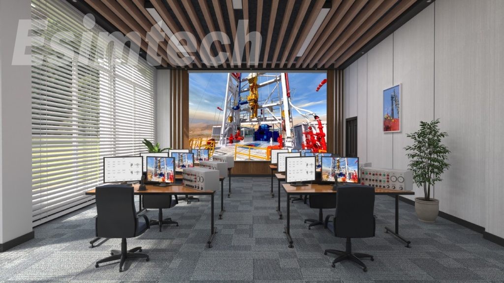
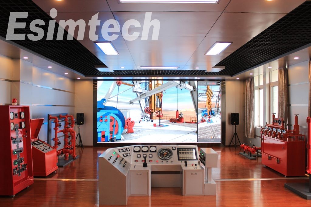
6. Display system adopts LED screen display
|
|
Large size LED true color display system • The 3D animation is displayed on LED true color display screen after process by professional graphics processor. • LED P2.5 screen,resolution:1920*1080 • LED screen size: 5400mm(wide)*3215mm(high) (The ultimate installation size and resolution will be depended on installation environment) |
2.2 System software
2.2.1 Oil recovery simulator technological software
(1) Software framework module
(2) Interface controlling module
(3) Flow calculating software module
(4) Device controlling software module
(5) Problem and trouble software module
(6) Sound effect controlling module software
(7) System self-checking module
2.2.2 Oil recovery simulator graphics software
(1) 2D flow controlling module
(2) 3D flow controlling module
(3) Device controlling module
|
SN |
Name |
Specification and technical parameters |
Unit |
Q’ty |
|
1 |
Oil and water well wellhead module |
Including rod-pumped well, screw pump well, electric submersible pump well and two water injection well and other wellhead accessories |
Unit |
1 |
|
2 |
Gauging station module |
Including feeding manifold, gauging and separating device, furnace anddosingtank |
Unit |
1 |
|
3 |
Water injection station module |
Including plunger pump, water pump and water injection manifold |
Unit |
1 |
|
4 |
Display system |
Large size LEDscreen |
Unit |
1 |
|
5 |
Controllingcomputer |
CPU: intel i5; Memory: 2G; Disk: 500G; Monitor:22-inch.(This configuration may be different according to the signed technical agreement) |
Set |
1 |
|
6 |
Graphics computer |
CPU: intel i7 or above; Memory: 4G; Disk: 500G; Graphics card: NVIDIA GTX 1060 or above; Monitor:22-inch.(This configuration may be differentaccordingto the signed technical agreement) |
Set |
1 |
|
7 |
Laser printer |
HPlaser printer. Printing speed: 16ppm; resolution: 600x600dpi |
Set |
1 |
|
8 |
Sound system |
American Crown amplifier; Behringertwo-channelspeaker; sound mixer, Takstar wireless microphone receiver (including wireless, hand, desk mounted, wearable microphone) |
Unit |
1 |
|
9 |
Other accessories |
Two chairs (rotatable, height adjustable), one desk, onesetof standard machine cabinet |
|
1 |
|
10 |
Installationandmaintenancetrainingplatform |
Providingoperationtraining |
|
|
|
11 |
Software |
Esimtech oil recovery simulator master control software |
Unit |
1 |
|
12 |
Software |
Esimtech oil recovery simulator technological software |
Unit |
1 |
|
13 |
Software |
Esimtech oil recovery simulator graphics software |
Unit |
1 |
3. System Function
3.1 Function and feature
(1) All devices of this system are the same as the real equipment in appearance,connecting way, as well as operation method.
(2) The system can figure out the working status, manifold pressure and so on at real time during student’s operation.
(3) 3D animation simulates the real site visualization. The system can present underground scene, device motion and device working theories.
(4) The systemhasvivid sound effect. Sound simulatedbythe system can start and stop according to student’s operation, working condition, as well as the graphics.
(5) The accident setting function enables students to judge the causeofthe accident directly, and helps them to master way of handling common accident.
(6) Oil well parameters are adjustable, including pressure, temperature, flow rate,etc.
(7) The functionofthe system isexpandable.
3.2 Training project
(1) Rod-pumpedwell opening
(2) Rod-pumpedwell shutting in
(3) Rod-pumpedwell washing
(4) Electric submersible well opening
(5) Electric submersible well shutting in
(6) Electric submersible well washing
(7) Screw pump well opening
(8) Screw pump well shutting in
(9) Screw pump well washing
(10) Checking pump condition by building pressure of screw pump well
(11) Wellhead fault judging and removing
(12) Starting furnace operation
(13) Single well gauging operation
(14) Washing gauging and separating device
(15) Gauging station fault judging and removing
(16) Water injection positive injection
(17) Waterinjection inverse injection
(18) Water injection process fault judging and removing
(19) Adjusting well injection water volume
(20) Building pressureofrod-pumped well wellhead
4. Technical Parameter and Operational Environment
4.1Technical parameter
(1) Power supply: 220V/50Hz AC
(2) Power consumption: <6000W
4.2 Operational environment
(1) Area: >=10*8.5m
(2) Separate equipment power supply from light power supply
(3) Working temperature:0℃~30℃
(4) Relative humidity:<90%
5. System Whole Layout and Program Interfaces
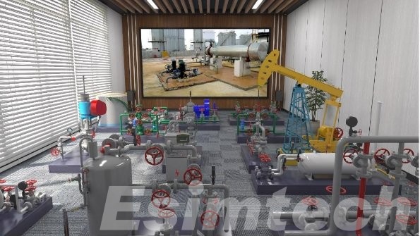
Figure 3 System whole layout with three-channel circular-screen projecting
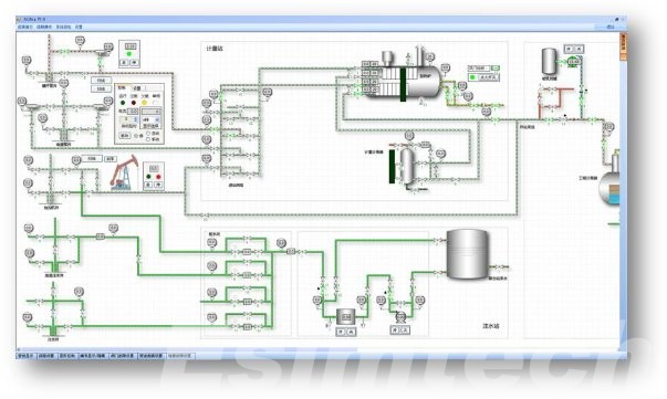
Figure 4 Program main interface on controlling computer
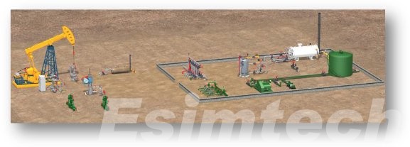
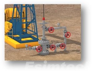
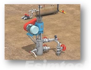
Figure 5 Graphics program running interfaces
System Features
- Real 3D, interactive animation
- Strict mathematical model, complying with real technical demands
- Device profile display and working principle analysis
- Intelligent scoring, fair and square
- Industrial PLC controlling, high stability and reliability
Parameters
| Operation voltage: | 220V 50Hz AC |
| Power consumption: | < 6000 Watt |
| Operating temperature | 0-30 ℃ |
| The average working time between malfunction: | ≥5000 hours |
Training Items
- Rod-pumped well opening
- Rod-pumped well shutting in
- Rod-pumped well washing
- Electric submersible well opening
- Electric submersible well shutting in
- Electric submersible well washing
- Screw pump well opening
- Screw pump well shutting in
- Screw pump well washing
- Checking pump condition by building pressure of the screw pump well
- Wellhead fault judging and removing
- Starting furnace operation
- Single good gauging operation
- Washing gauging and separating device
- Gauging station fault judging and removing
- Water injection positive injection
- Water injection inverse injection
- Water injection process fault judging and removing
- Adjusting well injection water volume
- Building pressure of rod-pumped well wellhead
Components
Why Choose Us?
- Cutomization
- Customized software and hardware
- Preciseness
- Precise mathematical and physical model
- Reality
- Highly realistic 3D scene display
F&Q
- Can this simulator replace the simulators I currently use in my good control training program?
Esimtech drilling and well control simulator has been approved by IADC and IWCF which can be used for common operation training, as well as IWCF and IADC training programs.
- Why is your simulator better than other simulators I’ve used in the past?
With the mission of “Assist training, reduce accidents and benefit the society”, Esimtech have been doing their best to design, develop and service every simulator. Esimtech simulator has its features as strictness, reliability, realisticness, lifelikeness. Problems and incident playback function enable trainees to experience troubles at any time which helps trainees to better master the skills of judging and handling common troubles.
- Do you have any happy clients or testimonials about your simulator?
“Creating value for customers”, which is always emphasized in our company. With this original intention, Esimtech Company develops simulators with high quality and provides timely and enthusiastic services. For all these years, the products and services provided by Esimtech are highly praised by our customers.
- Can you do custom work for my specific rig, company, or field?
Esimtech provides customization service, which is the biggest feature of the company. Esimtech has a strong production team skilled at programming and animation production. Both hardware and software can be customized to comply with the real situation.