A Deep Look into Well Control Fundamentals

Written By: Computer Science Professor
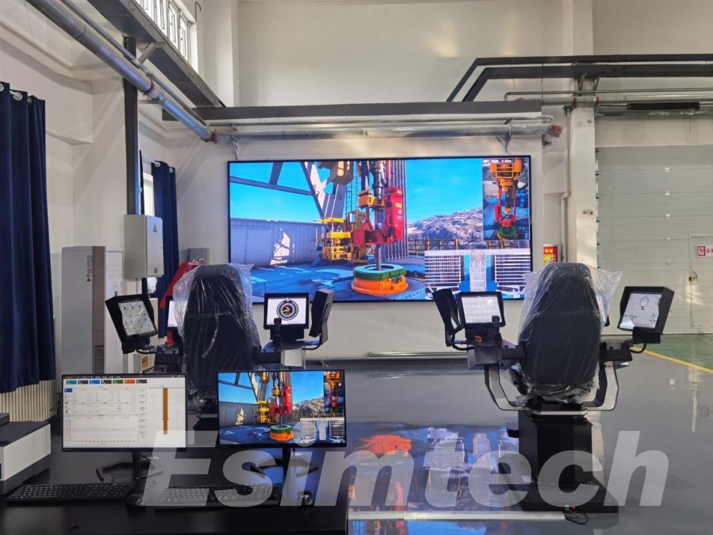
Deeply rooted in the R&D of simulators for the oil and gas industry, committed to bringing safety to every oil worker.
Ensuring well control is paramount in drilling operations. It’s the practice of maintaining pressure in the wellbore to prevent uncontrolled flow of formation fluids – oil, gas, or water – towards the surface. Losing well control, also known as a blowout, can have catastrophic consequences, causing environmental damage, endangering lives, and resulting in significant financial losses.
This article delves into the fundamental aspects of well control, equipping you with the knowledge to understand the mechanisms at play and the importance of proper wellbore management.

What are the Pressures in the Wellbore?
The success of well control hinges on a thorough understanding of the various pressures acting within the wellbore. Here’s a breakdown of the key players:
- Formation Pressure: This is the natural pressure exerted by the fluids (oil, gas, water) trapped within the rock formations surrounding the wellbore. Formation pressure is the driving force that pushes these fluids into the wellbore if an opportunity arises.
- Hydrostatic Pressure: This pressure is exerted by the drilling fluid (mud) against the wellbore walls. The weight of the mud column increases with depth, counteracting the formation pressure and preventing formation fluids from entering the wellbore. The density of the drilling mud is a crucial factor in determining the hydrostatic pressure it exerts.
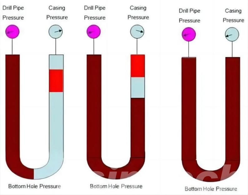
- Annular Pressure: This refers to the pressure exerted by the drilling fluid within the space between the drill pipe and the wellbore casing. Annular pressure plays a vital role in well control procedures used to manage kicks (influx of formation fluids).
- Bottomhole Pressure (BHP): This is the total pressure exerted at the deepest point of the wellbore. It is critical to maintain BHP high enough to balance formation pressure and prevent influxes.
Maintaining a balance between these pressures throughout the drilling process is the essence of well control. Any significant imbalance can lead to a well control incident.
What is the Well Control Barrier System?
The well control barrier system serves as the cornerstone of wellbore safety in drilling operations. It’s a meticulously designed and layered defense mechanism that works tirelessly to prevent uncontrolled flow of fluids from the formation into the wellbore. Let’s delve deeper into the individual components that comprise this crucial system:
1. Drilling Fluid
Drilling fluid, often referred to as mud, plays a multifaceted role in well control. It acts as the initial barrier between the wellbore and the formation, performing several critical functions:
- Hydrostatic Pressure Control: As discussed earlier, the weight of the drilling fluid exerts hydrostatic pressure. This pressure needs to be greater than the formation pressure to prevent formation fluids from entering the wellbore. By carefully adjusting the mud weight, well control engineers can maintain this crucial pressure balance throughout the drilling process.
- Wellbore Cooling and Cleaning: Drilling generates significant heat due to friction between the drill bit and the formation. The drilling fluid acts as a coolant, absorbing heat and preventing damage to the drill bit and other downhole equipment. Additionally, the mud carries rock cuttings (crushed rock fragments produced during drilling) back to the surface, keeping the wellbore clean and facilitating drilling progress.
- Formation Wall Support: Drilling fluids are formulated with specific properties to create a thin, filter cake on the wellbore wall. This cake acts as a barrier, helping to prevent formation fluids from migrating into the wellbore and also plays a role in stabilizing the wellbore by minimizing the risk of collapse in weak formations.
The properties of the drilling fluid – density, viscosity, lubricity, and filtration rate – are meticulously engineered based on the specific characteristics of the formations being drilled. Regular monitoring and adjustments to the mud properties are essential to ensure its effectiveness as a well control barrier.
2. Wellhead Equipment
The wellhead, located at the surface opening of the wellbore, houses critical equipment that provides essential control mechanisms:
- Blowout Preventer : This high-pressure valve system represents the primary defense against uncontrolled flow of fluids from the wellbore. A BOP stack typically consists of several individual BOPs, each serving a specific purpose:
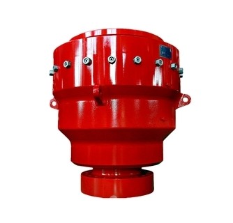
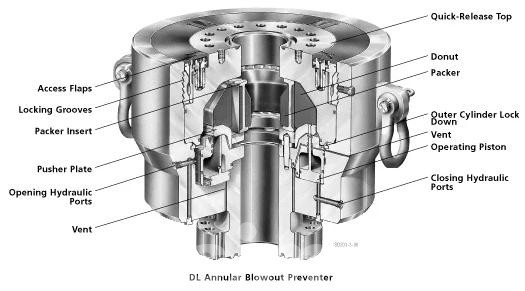
- Annular BOP: This BOP seals the space between the drill pipe and the well casing, preventing uncontrolled flow from the annulus (the space between the drill pipe and the casing).
- Ram BOP : This BOP utilizes hydraulic rams to seal off the wellbore by shearing and sealing the drill pipe. This allows for well control even with the drill pipe in the hole.
- Blind Shear RAM BOP: This BOP provides a complete wellbore seal by shearing and sealing off the wellbore completely, even without a drill pipe present.
- Hydram BOP (Accumulator BOP): This BOP utilizes a pressurized accumulator to provide a quick-acting seal on the wellbore in case of emergencies.
The BOP system is a complex array of valves and rams operated from a control panel at the surface. Regular pressure testing and maintenance of the BOP system are paramount to ensure their functionality in the event of a well control incident.
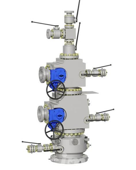
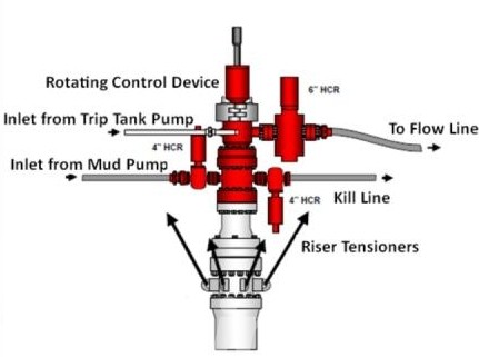
- Christmas Tree: Once the well transitions from drilling to production, the wellhead equipment becomes more elaborate, incorporating a system of valves and flow lines known as the Christmas tree. This complex network allows for controlled production of oil and gas while maintaining well integrity and providing well control capabilities.
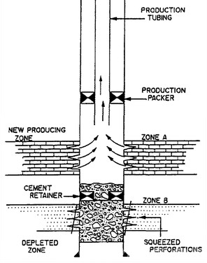
3. Casing and Cement
As the wellbore is drilled deeper, steel pipes called casing strings are installed at specific intervals. These casings serve two primary purposes:
- Structural Integrity: Casing strings provide structural support to the wellbore, preventing collapse due to the pressure exerted by the surrounding formations. The diameter of the casing decreases with depth, as each new section is installed within the previous one.
- Isolation of Formations: Casing strings isolate different sections of the wellbore, preventing fluids from migrating between formations. This is crucial for well control and zonal isolation, which ensures that fluids are produced only from the targeted formation.
The space between the casing and the wellbore is filled with cement, forming a strong and impermeable barrier. This cement sheath provides additional structural support and prevents fluids from migrating between formations or into the wellbore through weak zones in the rock.
How Many Well Control Methods?
When a kick (influx of formation fluids) disrupts the wellbore pressure equilibrium, well control procedures swing into action. These procedures rely on a combination of well control methods to regain control of the well and safely circulate the kick out. Here’s a detailed breakdown of the most common well control methods, along with their strengths and limitations:
1. Driller’s Method (Circulating While Drilling – CWD):
- Execution: The driller’s method, also known as circulating while drilling (CWD), is the simplest and most commonly used method for handling small kicks. It involves two key steps:
- Slow Down and Increase Pump Rate: The driller gradually reduces the drilling rate or pauses drilling altogether. Simultaneously, the mud pump rate is increased to circulate the kick fluid (formation fluids entering the wellbore) out of the wellbore and back to the surface.
- Maintain Annular Pressure: Throughout the process, it’s crucial to maintain adequate annular pressure (pressure exerted by the drilling fluid in the space between the drill pipe and casing). This pressure helps to contain the kick and prevents further influx of formation fluids.
- Strengths: The driller’s method is a straightforward and efficient approach for handling minor kicks. It requires minimal wellbore manipulation and can be implemented quickly.
- Limitations: This method is only suitable for small kicks. For larger kicks, the increased pump rate needed to circulate the kick out can lead to exceeding formation fracture pressure, potentially causing even greater wellbore instability issues. Additionally, the driller’s method requires close monitoring of annular pressure and may not be effective in highly fractured formations where wellbore communication paths exist.
2. Wait and Weight Method (Shut-In, Drill Pipe Pressure Method):
- Execution: The wait and weight method, also known as the shut-in, drill pipe pressure method, is a more deliberate approach used for moderate-sized kicks. Here’s a step-by-step breakdown:
- Shut-In the Well: The well is shut-in by closing all wellbore openings, including the blowout preventer (BOP) stack. This isolates the kick from the surface and prevents further influx of formation fluids.
- Monitor Pressures: Downhole pressure gauges are monitored closely to track the pressure behavior of the kick. As the kick equalizes with the hydrostatic pressure of the mud column, the pressure readings will stabilize.
- Wait and Evaluate: Once the pressures stabilize, a period of waiting allows the kick to fully equalize. During this time, wellbore stability and other factors are evaluated to determine the appropriate course of action.
- Increase Mud Weight (Weight Up): Once deemed safe, the mud weight is gradually increased. This creates a higher hydrostatic pressure that can safely contain the kick and allow it to be circulated out of the wellbore.
- Strengths: The wait and weight method offers greater control over the kick compared to the driller’s method. It allows for pressure stabilization and wellbore evaluation before proceeding with kick circulation.
- Limitations: This method requires shutting in the well, which can lead to a temporary halt in drilling operations. Additionally, if the kick is not circulated out promptly, it can lead to wellbore pressure imbalances and potential wellbore instability.
2. Concurrent Method (Managed Pressure Drilling – MPD):
- Execution: The concurrent method, often used in conjunction with Managed Pressure Drilling (MPD) techniques, offers a more sophisticated approach for handling kicks in challenging wellbore environments. Here’s a simplified explanation:
a. Maintain Constant Bottomhole Pressure (BHP): MPD allows for real-time monitoring and control of the bottomhole pressure (BHP) at the drill bit. During a kick, the MPD system automatically adjusts surface pressures to maintain a constant BHP.
b.Circulate the Kick: While maintaining BHP, the kick is circulated out of the wellbore by adjusting mud pump rate and other drilling parameters.
- Strengths: The concurrent method provides the most precise control over wellbore pressure during a kick. It is particularly useful in highly fractured formations or situations with narrow pressure margins.
- Limitations: This method requires specialized MPD equipment and expertise. Additionally, the complex nature of MPD systems can introduce potential operational challenges.
What is Kick Detection and Well Control Procedures?
A wellbore can be likened to a pressurized pipe extending deep into the earth’s crust. Maintaining control of this pressurized environment is paramount, and any influx of unwanted formation fluids can lead to a serious well control event. Here, we delve deeper into the crucial aspects of kick detection and well control procedures:
1. Kick Detection: Spotting Trouble Early
Kick detection forms the cornerstone of well control. A kick refers to the unwanted influx of formation fluids (oil, gas, water) into the wellbore while drilling. Early detection is critical for minimizing the severity of the kick and facilitating a safe and efficient well control response. Here are the primary methods employed for kick detection:
- Pit Gain Method: This is the most basic method. The mud level in the pits (large tanks that hold the circulated drilling fluid) is continuously monitored. A sudden increase in the pit level can indicate a kick, as the influx of formation fluids displaces the drilling fluid in the wellbore.
- Flow Rate Monitoring: The flow rate of drilling fluid exiting the wellbore is constantly measured. An unexpected increase in flow rate can be a sign of a kick, as the formation fluids contribute to the overall flow.
- Annular Pressure Monitoring: Pressure sensors monitor the pressure of the drilling fluid in the annulus (space between the drill pipe and the casing). During a kick, the influx of formation fluids can cause a decrease in annular pressure.
- Early Kick Detection (EKD) Systems: These advanced systems utilize sophisticated algorithms to analyze multiple wellbore parameters (pressure, flow rate, mud properties) in real-time. They can detect subtle changes that might indicate an incipient kick, allowing for a faster response.
The effectiveness of kick detection relies on a combination of these methods and the vigilance of the drilling crew. It’s crucial to establish appropriate kick detection criteria based on the wellbore conditions and drilling parameters.
2. Well Control Procedures: Regaining Command
Once a kick is detected, immediate action is required to regain control of the wellbore and prevent a blowout. Well control procedures follow a systematic approach, involving three primary stages:
- Shut-In: This is the first and most crucial step. The objective is to isolate the kick by closing all wellbore openings at the surface. This typically involves closing the blowout preventer (BOP) stack, effectively sealing the wellbore and preventing further influx of formation fluids.
- Circulation: With the well shut in, the next step is to circulate the kick out of the wellbore. This involves pumping drilling fluid down the drill pipe and returning it to the surface via the annulus. The heavier mud weight of the drilling fluid helps to displace the lighter formation fluids and restore wellbore pressure control.
There are different circulation methods employed depending on the severity of the kick and wellbore conditions:
a. Driller’s Method: Suitable for small kicks, this method involves slowing down or stopping drilling and increasing the mud pump rate to circulate the kick out.
b.Wait and Weight Method: For more significant kicks, drilling is stopped, and the well is shut in. Once pressures stabilize, additional weight is added to the drilling fluid by mixing in heavier materials. The well is then carefully reopened, and the heavier mud is circulated to displace the kick.
c. Circulate While Drilling (CWD): This advanced method involves continuing drilling while simultaneously circulating the kick out. CWD requires specialized equipment and precise control of mud properties and circulation rates. It is typically used for experienced crews and under specific wellbore conditions.
- Well Killing: Once the kick has been circulated out, the well is deemed “killed.” This final step involves permanently sealing the wellbore to prevent future influxes. In some cases, this might involve pumping heavy cement down the wellbore to establish a permanent barrier between the formation and the wellbore.
The specific well control procedures employed will depend on the severity of the kick, the wellbore conditions, and the available resources.
By recognizing the importance of kick detection and understanding the well control procedures, wellbore operations can be conducted with greater safety and efficiency.
What is Well Control Equipment?
Within the well control arena, specialized equipment safeguards well integrity and combats uncontrolled fluid flow. These tools work alongside drilling fluids and wellbore barriers to create a robust defense system.
1. Blowout Preventer (BOP) Stack: The BOP stack stands guard at the wellhead, serving as the primary physical barrier against uncontrolled flow. It’s a complex system of multiple BOPs, each with a specific function
2. Choke Manifold and Choke Valves: The choke manifold precisely regulates wellbore fluid flow. Choke valves located within the manifold are crucial for well control procedures, allowing for controlled circulation of kick fluids during well control operations and regulating flow during production.
3. Kill Lines and Valves: Kill lines are high-pressure pipelines that pump heavy kill fluids (often cement) down the wellbore to permanently seal it in emergencies. Kill valves located at the surface wellhead control the flow through these lines.
4. Pressure Gauges and Monitoring Systems: Continuous pressure monitoring is paramount for well control. Pressure gauges and advanced monitoring systems provide real-time data on wellbore pressure, essential for wellbore pressure management, kick detection, and implementing well control procedures.
In essence, well control equipment forms the foundation of a well control program, working in tandem with other well control measures to ensure safety and environmental protection.
Well Control Training and Regulations
Well control training programs are essential for ensuring that personnel involved in drilling operations are adequately trained to respond to well control incidents effectively. These programs cover theoretical knowledge, practical skills, and emergency response procedures. Training may include classroom instruction, simulations, and hands-on exercises conducted by certified instructors.
Regulatory bodies such as the International Association of Drilling Contractors (IADC) and the American Petroleum Institute (API) establish industry standards and best practices for well control operations. These regulations outline requirements for well control training, competency assessments, equipment standards, and emergency response protocols. Compliance with these regulations is mandatory for operators and drilling contractors to ensure the safety and integrity of drilling operations.
Additionally, regulatory agencies such as the Occupational Safety and Health Administration (OSHA) in the United States and similar organizations worldwide enforce well control regulations and conduct inspections to ensure compliance with safety standards. Violations of well control regulations can result in fines, penalties, and legal consequences for operators and drilling contractors.