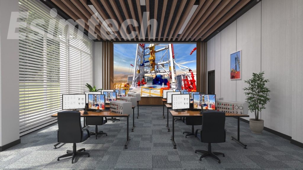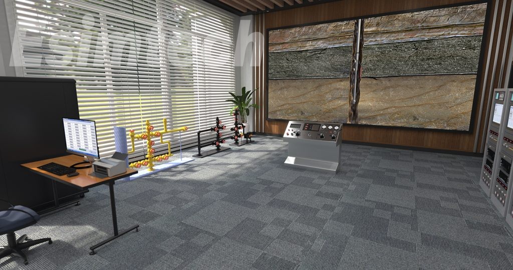
ESIM-FWL2 Production Well Logging Simulator
- Cutomization
- Customized software and hardware
- Preciseness
- Precise mathematical and physical model
- Service
- Timely and considerate after-sale service
Production well logging simulation training system takes the advantage of computer simulation and virtual reality, network technology, graphics technical, multi-media technical and well logging theory to solve the problem of pre-post training and skill evaluation of well-logging technicians and workers and make training and evaluation keep step with the technology development and production demand.
System Features
- Actual 3D interactive animation
- Lifelike environment noises and voice prompt
- Strict mathematical models, conforming to real technology demands
- Systematic and complete training content, flexible project configuration
- Intelligent scoring, fair assessment
- Advanced software, friendly interface
- Industrial PLC control with high stability
1. Introduction
Petroleum logging operation is a complicated,consumable and demanded work.Therefore,the operation skill and competency of the operator is very important.While,traditionally training of the workers is with high risk and costs much time;and also,traditional training cannot playback accidents and special working conditions,and cannot objectively evaluate worker’s operation.Production well test simulation training system takes the advantage of computer simulation and virtual reality,network technology,graphics technical,multi-media technical and well logging theory to solve the problem of pre-post training and skill evaluation of well logging technicians and workers and make training and evaluation keep step with the technology development and production demand.
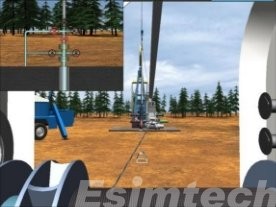
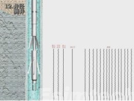
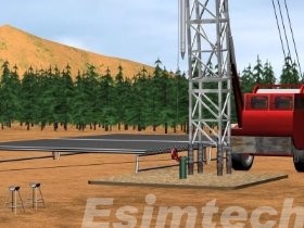
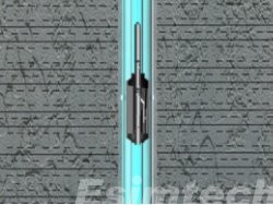
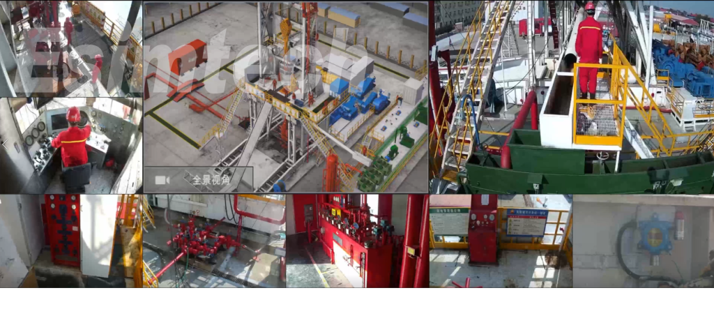
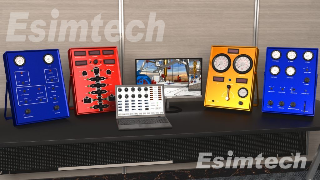
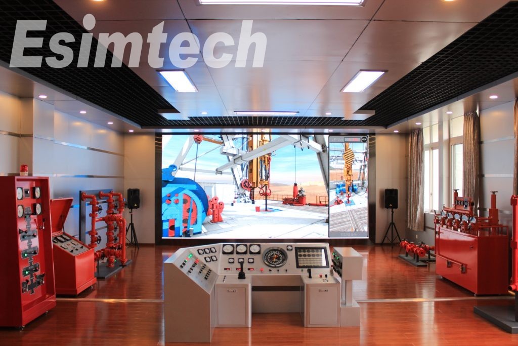
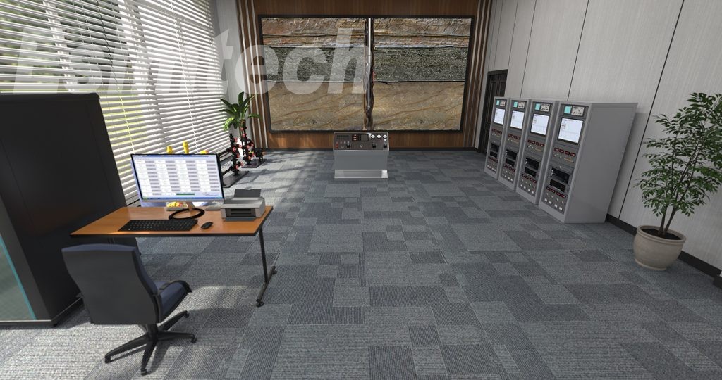
This system uses 3D animation to display structure and working theories of various well logging devices, and the whole well logging process. It can provide training and test of operation on well head of oil well, water well and gas well; training and test of raising and lowering of drawworks, lowering with block, raising with stuck; training and test of theoretical knowledge. The system is composed of well logging surface unit, drawworks console, oil well, water well, gas well, graphics system and accessory software. All the consoles in the system are similar to real equipment. All panel layout, operation methods and parameter display are the same as the actual devices. Virtual reality technology and 3D animation, combined with lifelike sound effect, make up an immersive training environment.
This system has online examination system on well lolling theory, 17 3D teaching animation of well logging technology, operation training and test system of the three kinds of wellhead, training and test system of 4 drawworks operation, training and testing of 9 well logging technology including injection well, withdrawal well and engineering well, as well as students managing system. The system can also be customized according to the user’s requirements.
2. System Component
2.1 Major Hardware
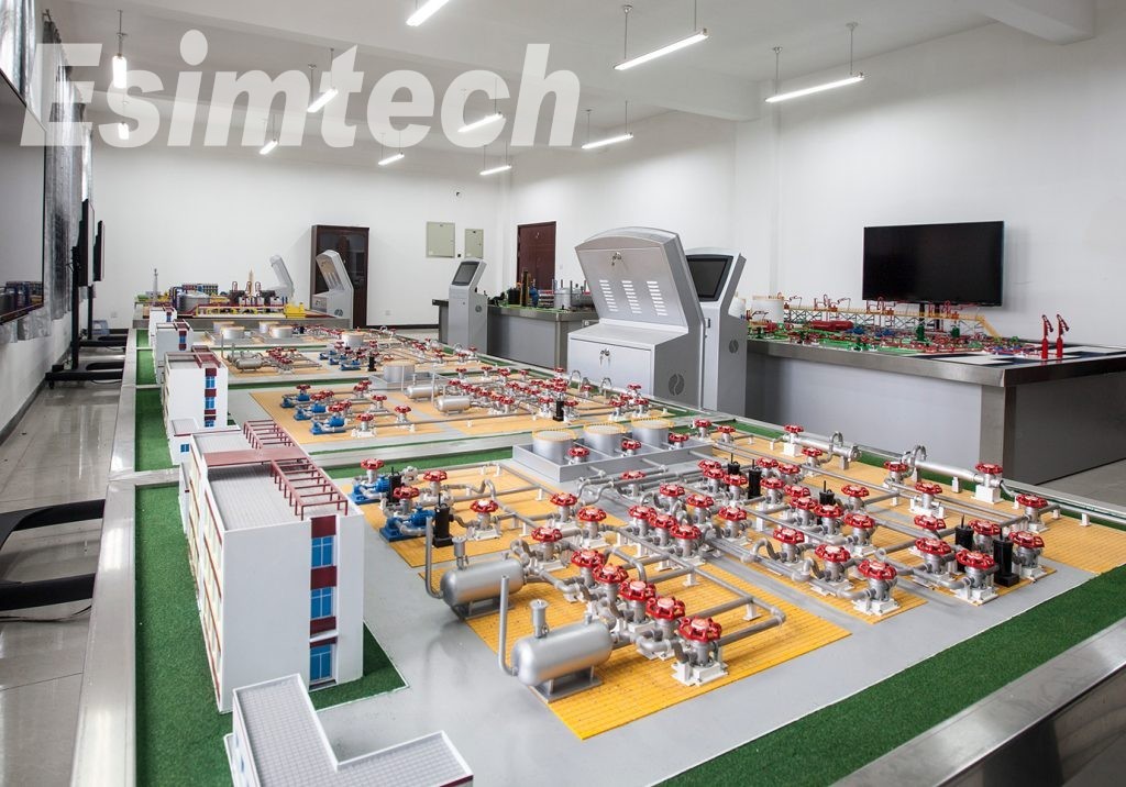
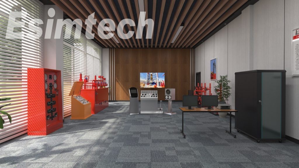
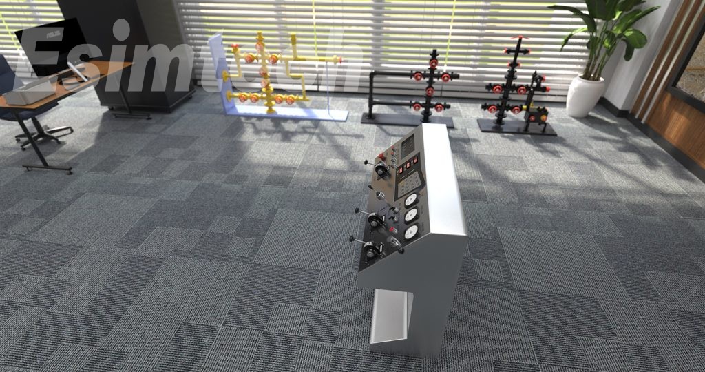
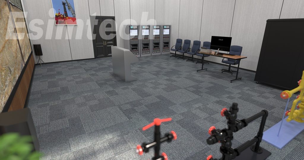
Production well test simulation system has a set of consoles which are the same as the real well logging equipment on well logging site, which provide a training environment with high fidelity. Adopting the distributive three-level network structure, the system structure is as show in figure 1.
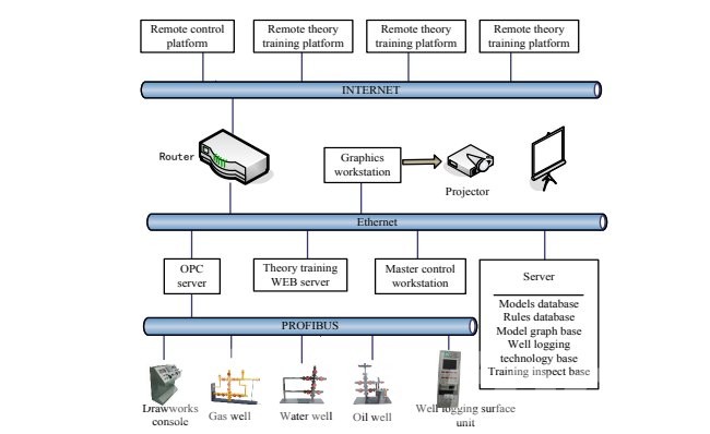
Figure 1 Production well test simulation system structure
1. Well logging surface
Well logging surface unit simulates the panel functions and software function of real surface instrument,including oscilloscope,monitor,compound control box,cable core shift switch,AC/DC power of underground equipment,annular power,engineering control computer,thermal printer,etc.The surface unit receives the simulation signal of underground equipment,completes the processing,displaying,recording and printing of the simulation signal,and sends signals,operation information of operator,parameter setting information to database server.
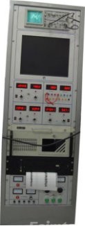 | Made of metal,designed according to PL2000 well logging surface system,and panel function of other well logging surface system,simulating various testing method,technological process,producing of signals,curves and the initial judgment of well logging quality. |
2. Drawworks console
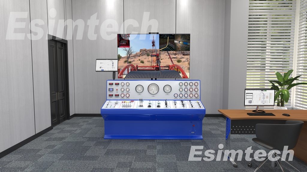
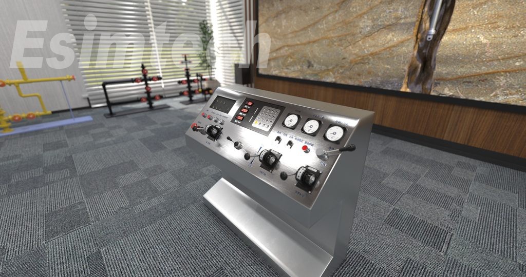
Drawworks console takes Oehman’s apparatus drawworks as prototype. The drawworks panel, operation method and function of operation engines are the same as real drawworks, mainly including drum control lever, throttle lever, brake lever, system pressure regulating valve, emergency on-off valve, hydraulic motor speed switch, transmission position switch, engine unit meter, oil pressure meter, system pressure meter, etc.
Drum lever, throttle lever and brake lever are the key devices on drawworks console, and the data of the two levers are acquired by PLC through simulation input module. Push drum lever, and the drum will rotate forward. Lower the cable, and the more the drum lever is pushed, the faster the drum will rotate. Pull backward the drum lever, and the drum will rotate backward. Raise the cable, and the more the drum lever is pulled, the faster the drum will rotate. Push throttle lever, and motor rotation speed will increase, and drum rotation will be faster. Simulated motor noises changes as the motor rotation speed. The rotation speed will also be displayed on the motor rotation speed meter. Push brake lever, the braking force increases, and drum rotation speed decreases, and finally stops.
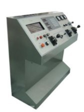 | Made of metal,designed according to Oehman’s apparatus drawworks;The drawworks panel,operation method and function of operation engines are the same as real drawworks.Simulating analytical judging and handling of running and pulling testing devices control,system tension control,testing device stuck and well logging accidents. |
- 3. Wellhead device
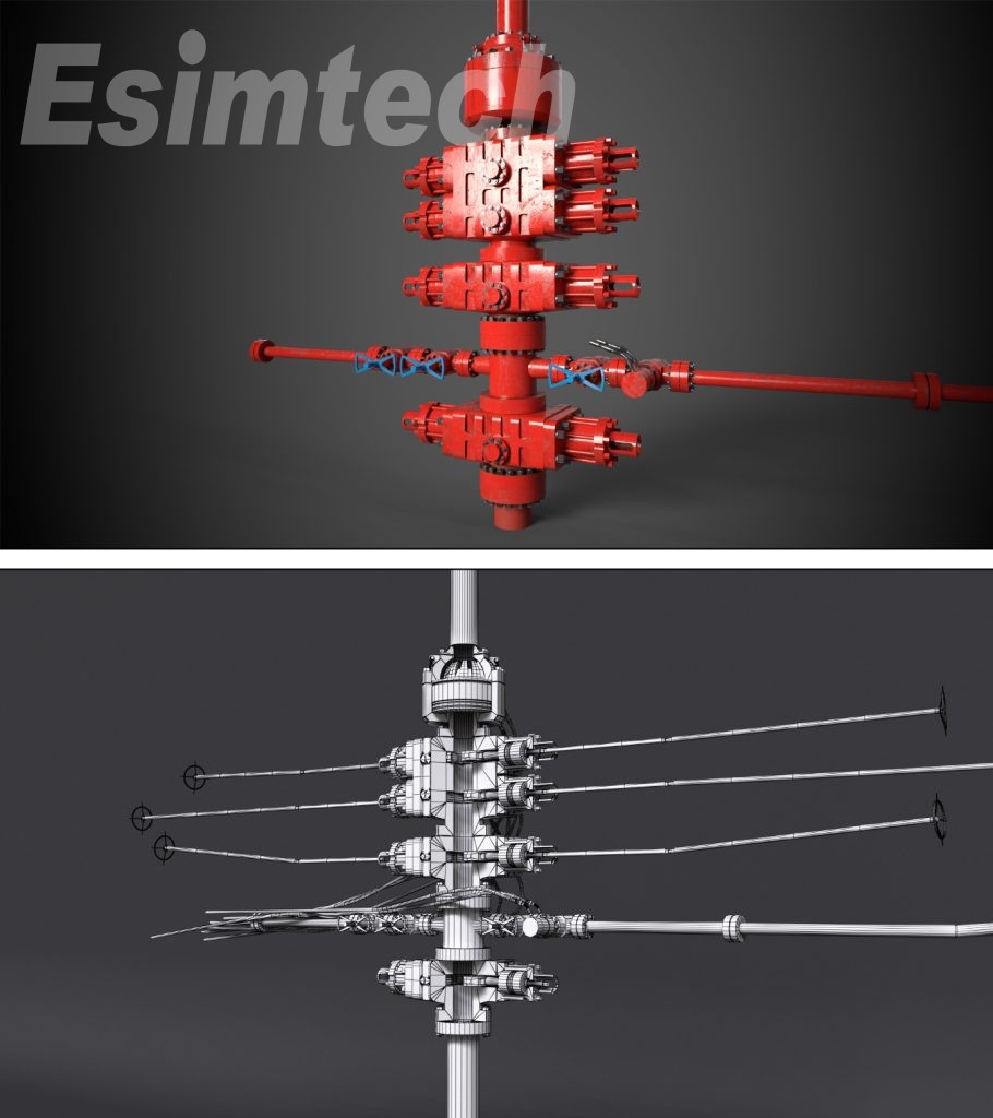
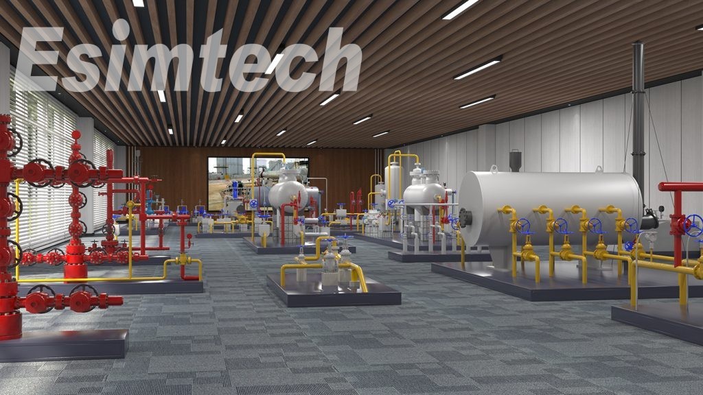
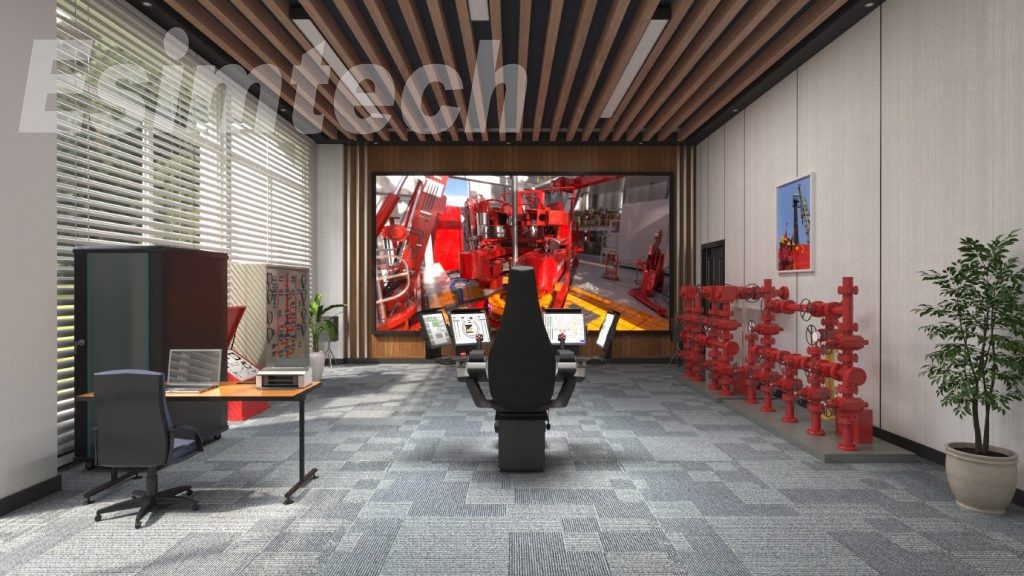
Wellhead devices include oil well, gas well and water well wellhead, simulating the operating of real site wellhead, reflecting the state of wellhead valves and operation rules of wellhead worker. The devices are made by ABS engineering plastic which is easy for installation and transportation. Each wellhead device is fixed on a bracket made by super cold rolled steel plate which is designed into iron-gray baking varnish.
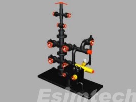 | Oil well wellhead deviceThis device is made as the real casing and tubing by 1:1.It is painted gray,which is the same as the real equipment,including the eccentric testing wellhead valve,tubing emptying valve,tubing producing valve,casing emptying valve,casing producing valve and wellhead manifold. |
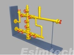 | Gas well wellhead deviceThis device is made by scale of 1:2 with real equipment.This gas well wellhead omitted the valve at the bottom.It is painted yellow,which is the same as the real site equipment.The manifold diameter is the same as oil well and gas well tubing.It has no insulating part |
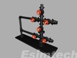 | Water well wellhead deviceThe size and color of this device is the same as the real equipment.It is painted green.It includes master valve,testing valve,tubing emptying valve,tubing injecting valve,casing emptying valve,casing injecting valve and wellhead valve. |
The displaying system adopts large size LED screen solution.
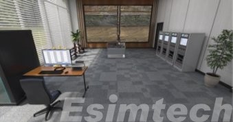 | Large size LED screen display system•The 3D animationisdisplayed on large size LED screen after processed by professional graphics processor.•LED P2.5 screen; Resolution: 1920*1080•Screen size: 5400mm(W)*3215mm(L)(The ultimate installation size and resolution will be depended on installation environment) |
2.2 System Software
2.2.1 Master Control Software
- Platform software module
- Instructor station software module
- Student console software module
- Wellhead operation software module
- Drawworks worker operation software module
- Operator training software module
- Team operation software module
- Theoretical training and examining software module
- System self-checking module
2.2.2 Graphics Software
- Virtual 3D scene displaying software module
- Multi-media animation
3. System Function
3.1 Function and Feature
- The simulation training system takes the real well logging equipment as prototype. The levers, meters, switches and operation rules are the same as the real equipment, which makes up a full size and real device operation environment
- This system adopts strict mathematical simulations, presenting the trends of important parameters in the form of curves, which complies with the real technical requirement.
- The training content is systematical, completed, and can be configured flexibly, which solves the problems of time wasting, high risk, and unable to playback accident and special working condition of traditional training
- This system has automatic scoring function. It can evaluate students’ operation procedure and level, and can give out point deducting reason, which will be objective enough in students’ evaluation.
- Online examination completes the theory testing of students and gives points automatically
3.2 Training Projects
1. Wellhead workers operation training
1)Tubing injecting operatio nwithtest valve at wellhead
2)Tubing injecting operation without test valve at wellhead
3)Casing injecting operation with test valve at wellhead
4)Casing injecting operation with test valve at wellhead
5)Pumping operation with value at wellhead
6)Pumping operation with test valve at wellhead
2. Drawworks worker operation training
1)Normal lowering
2)Normal raising
3)Lowering with obstacle
4)Raising with obstacle
3. Operator operating training
1)Five-parameter combination logging
2)Electromagnetism flow logging
3)Oxygen activation logging
4)Impedancelogging
5)Audio logging
6)Caliper logging
7)Singlemagnetic locating logging
8)Former magnetic locating logging
9)Acoustic logging
4. Team operation training
1)Five-parameter combination logging
2)Electromagnetism flow logging
3)Oxygen activationlogging
4)Impedance logging
5)Audio logging
6)Caliper logging
7)Singlemagnetic locating logging
8)Former magnetic locating logging
9)Acoustic logging
5. 3D animation ofwelllogging technological process
4. Technical Parameters and Operational Environment
4.1 Technical Parameters
(1) Powersupply:110~220V/50~60Hz AC
(2) Power consumption: <5000W
4.2 Operational Environment
(1) Area: >=10*8.0m
(2) Separate equipment power supply from light power supply
(3) Working temperature:0℃~30℃
(4) Relative humidity: <90%
5. Program Interfaces
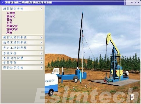
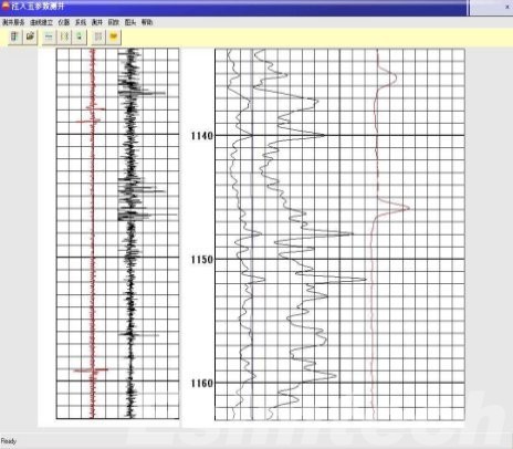
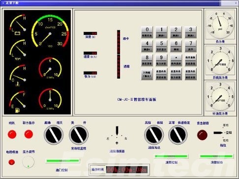
Figure 3 Graphics program interfaces
Components
F&Q
- How would I get the simulators if I ordered?
The package will be shipped to the customer’s facility. If necessary, Esimtech provides onsite installation and training services.
- Do you have any after-sale service?
Esimtech provides lifetime service support via phone, email or fax at no cost. The simulator is under warranty for a period of 12 months, including updates if released during the warranty period.
- Do you have any certifications?
Esimtech drilling and well control simulator has been approved by IWCF and IADC.
Since establishment, Esimtech has obtained a series of independent intellectual property rights, including invention patents in China and abroad.
Esimtech was granted as “High-tech Enterprise”, and has been awarded the third prize of “Science and Technology Progress”.
Esimtech has also obtained the certificates of ISO 9001, ISO14001 and ISO45001.
- Do you have simulators simulating offshore drilling platforms?
Esimtech provides drilling and well control simulator with offshore platform simulation.
- Is there a complete instruction for use if I ordered?
There will be completely operational instruction and maintenance instruction along with the package.

