How to Maintain and Calibrate Physical Consoles on Full-Scale Drilling Simulators

Written By: Computer Science Professor
Deeply rooted in the R&D of simulators for the oil and gas industry, committed to bringing safety to every oil worker.
A full-scale drilling simulator seems to be functioning normally, but the actual control inputs may have already deviated. Smooth movement of the joystick, responsive rotation of the controller, and normal operation of the display do not necessarily mean that the actual position of the controller is still completely consistent with the values read by the simulation system.
Therefore, maintaining the physical control console is not just about cleaning buttons, switches, and panels; it is more important to ensure that the operator’s actions are consistent with the responses of the simulator.
Regular inspections, calibrations, and systematic troubleshooting help to ensure that the console remains reliable and accurate.
What Should You Check on a Physical Drilling Simulator Console?
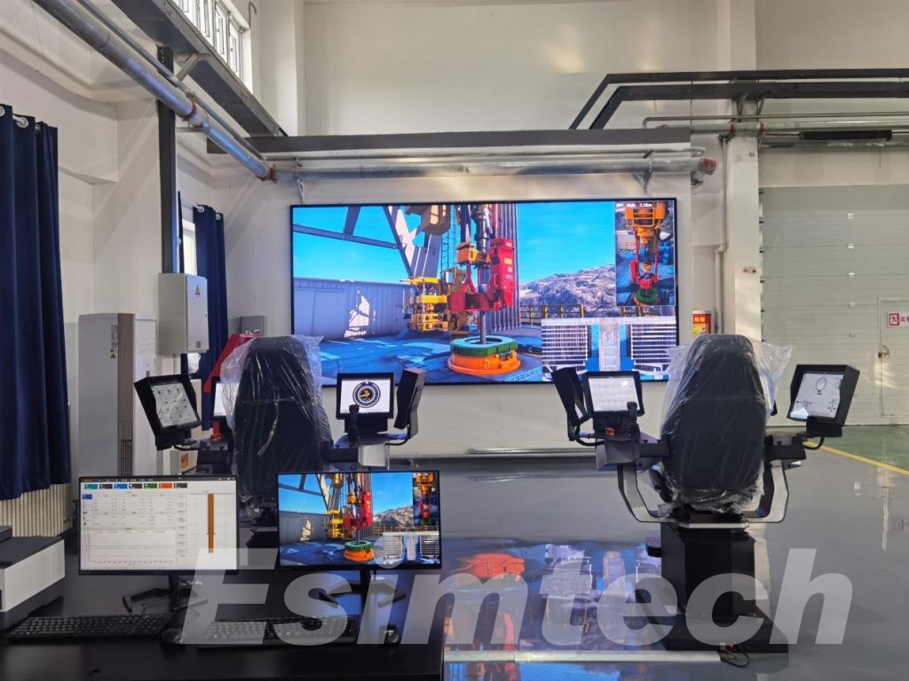
The actual operation inspection should cover three aspects: mechanical condition, electrical condition and functional response.
- Mechanical condition
Check whether the physical control devices are present without any issues such as:
- Stuck or excessive resistance
- Abnormal movement or noise
- Damaged switches or buttons
- The control lever or control rod cannot return to the normal position
- Loose knobs, handles or panel components
Before training, the display screen, indicator lights and emergency control devices should also be checked.
- Electrical condition
Check:
- Connector and cable connection
- Line damage or loosening
- Oxidation or poor contact
- Intermittent signals
- Abnormal changes in input readings
For example, the physical control device may seem normal, but a loose connector could cause unstable signals.
- Function response
This is the most crucial check: Can the simulator respond correctly to physical input?
After operating the control device, there should be expected changes in the corresponding simulated parameters or device behavior. The fact that the control device can move or that the indicator lights are properly illuminated does not mean that its function is normal. The simulator must also correctly identify and process the input signals.
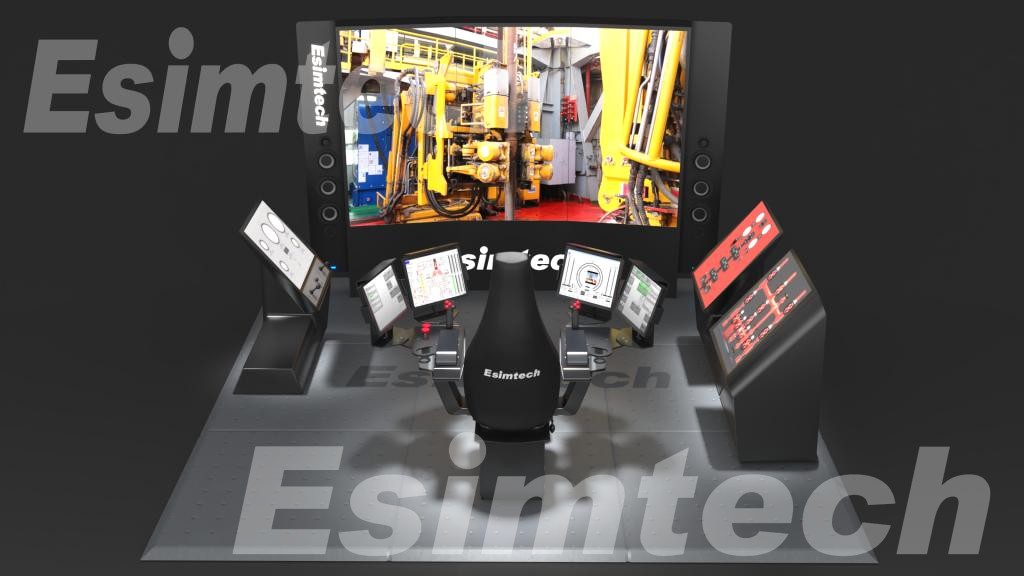
When Does a Physical Console Need Calibration?
Maintenance and calibration address different issues.
Maintenance ensures the reliable operation of the hardware, while calibration verifies the accuracy of the input.
Even if the mechanical structure of the controller is intact, if the zero position, operating range, or signal output deviates, it is necessary to recalibrate.
The following situations should be considered for calibration:
- Continuous output of incorrect values by the controller
- Change in zero position or middle position
- Incompatibility between input range and configured range
- Replacement of sensors, potentiometers, encoders, or other input components
- Occurrence of abnormal signals
- Manufacturer’s requirement for regular verification
For example, a rotating controller may still be able to smoothly move from the minimum value to the maximum value, but the zero position has shifted. At this point, the simulator may recognize the same physical position as a different command.
It should also be noted that calibration cannot be used to compensate for defective components.
If the controller has wear, instability, or intermittent faults, the hardware problem should be addressed first. The purpose of calibration is to verify whether the components are functioning properly, rather than masking the faults.
How to Calibrate and Verify Console Inputs
Calibration should be verified along the complete signal path:
Physical control → Electrical signal → PLC/inputs → Simulation software → Display parameters or simulation response
Actual calibration can be divided into four stages:
1. Check the neutral position: Set the controller to the normal zero position or neutral position, and confirm that the values recorded by the simulator are consistent with the configured reference values.
2. Check the working range: Test the entire working range, not just the endpoints. Low, neutral, and high range tests help detect signal drift or non-linear responses.
3. Compare input with simulation output: The physical input should generate the expected parameter changes or device behavior. The signal reaching the PLC does not mean that the entire system has been correctly calibrated.
4. Record the results: Effective calibration records should include:
- Console or component
- Check date
- Expected value
- Actual value
- Adjustment content
- (If applicable) Replaced components
- Technicians
- Next verification date
These records can serve as a benchmark for subsequent inspections and help identify minor changes.
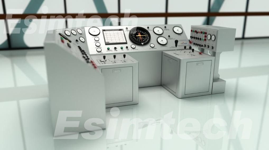
How to Diagnose Console Problems Before They Become Downtime
When a fault occurs, recalibration is not always the best solution. First, it is necessary to determine at which stage of the signal path the problem lies.
The following three common situations can be mainly distinguished:
| Symptom | First Areas to Investigate |
| No response | Control, wiring, PLC input |
| Unstable response | Connectors, wiring, input component, electrical interference |
| Consistently incorrect value | Zero position, scaling, calibration, signal mapping |
This method helps to narrow down the scope of the fault before modifying the settings.
For example, if the controller does not receive a signal at the PLC input terminal, recalibrating the software cannot solve the problem. Instead, if the PLC has received the correct signal but the analog parameters are still incorrect, further checks should be made on the downstream signal mapping or simulation logic.
This distinction can reduce unnecessary downtime and also avoid repeatedly adjusting components that do not cause the fault.
Building a Preventive Maintenance Routine for Long-Term Reliability
Preventive maintenance should be an integral part of the simulator’s daily operation, rather than a temporary measure taken after a failure occurs. The maintenance plan should be formulated based on the actual training duration, operating conditions, component wear, and manufacturer recommendations.
The quick functional checks before each training session can be combined with regular detailed inspections. Operators are responsible for checking control responses, displays, indicator lights, and emergency functions; qualified technicians regularly inspect wiring, connectors, input signals, and calibration status. After replacing input components, functional verification should be conducted, and recalibration may be necessary if required.
Maintenance records should be kept throughout the entire usage period of the simulator. Tracking repeated adjustments and failures helps to detect component deterioration in advance and reduces unexpected downtime.
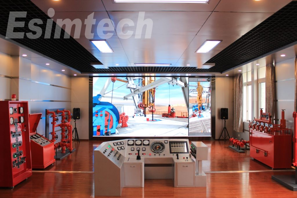
Final
For the training center that invests in building a full-scale drilling simulator, in addition to authenticity and functionality, maintainability is also crucial. The full-scale drilling simulator of ESIMTECH integrates an actual drilling control console, a control system based on industrial PLC, real-time parameter display and system self-checking functions, providing a realistic operation environment for training and supporting long-term and reliable operation.