How to Maintain Equipment for Well Control Operations

Written By: Computer Science Professor
Deeply rooted in the R&D of simulators for the oil and gas industry, committed to bringing safety to every oil worker.
In the highly-stakes field of oil and gas drilling, the goal of well control is to prevent the uncontrolled releases of fluids from formation and blowouts. While a thorough training program and quick decision-making are vital but they’re unusable if the equipment designed to seal and divert pressure fails. So, regular, systematic maintenance of equipment during well control operations is the base upon which operational security is constructed.
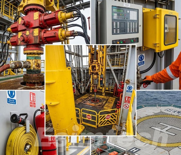
Key Equipment during Well Control Operations
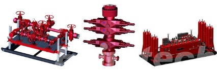
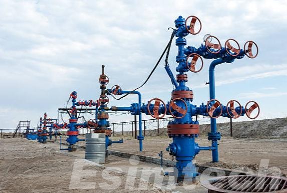
Before discussing strategies for maintenance, it is important to identify the assets that are being scrutinized. The equipment for controlling the well, typically located in the blowout preventer(BOP) stack.
This chart reflects the standard well control equipment for the majority of modern drilling operations, but particular arrangements, the pressure rating and stack configurations will differ in accordance with the depth of the well formation pressure, well depth and the regulatory jurisdiction.
| Equipment Category | Specific Component | Key Function |
| Primary Sealing Equipment | Annular BOP | The seal is able to be placed around the entire size pipe, or even the drilling string; great for the stripping process or turning pipe when under pressure. |
| Pipe Ram BOP | Utilizes two blocks that have semicircle cutouts that seal around a certain dimension of the drill pipe. | |
| Blind Ram BOP | Completely clear wellbore (no pipe in the). | |
| Shear Ram BOP | Cuts through the pipe and seals across the bore during an emergency situation. | |
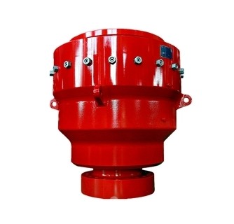
| Hydraulic Power & Control | Accumulator Unit | It stores high-pressure hydraulic fluid that can instantly close BOPs when the rig’s electrical power is cut off. |
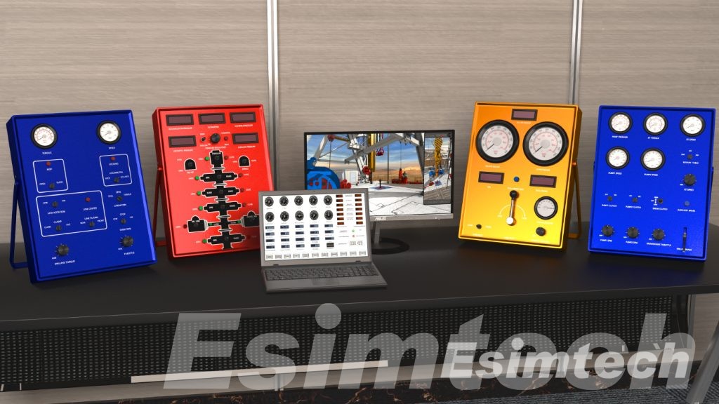
| Driller’s Control Panel | The main station located on the floor of the rig, from where the driller can activate BOP functions. | |
| Remote Control Panel | A backup panel that is usually placed in a secure area far from the floor of the rig to be activated in the event of an emergency. | |
| Flow & Pressure Routing | Choke Manifold | A series of chokes and valves redirects well fluids away from the BOP stack, and precisely regulates backpressure. |
| Adjustable Choke | The main component in the choke manifold, which produces an adjustable orifice to regulate flow rate and pressure in the casing. | |
| Kill Manifold | A high-pressure pipe and valve assembly that pumps massive (kill) dirt into the well, below BOP rams. BOP rams. | |
| Monitoring & Fluid Handling | Trip Tank | Accurately monitors small variations in the volume of mud in order to determine if there is a kick the pipe is tripping out or in through the hole. |
| Mud Gas Separator (Poor Boy Degasser) | Securely releases flammable gas from mud coming from a kick keeping gas out of the shakers. | |
| Standpipe Pressure Gauge | Displays the pressure of the pump while the pump is in circulation; crucial to calculate the pressure of the bottom hole during the kill process. | |
| Internal String Control | Casing Pressure Gauge | Monitors pressure between BOP RAMS and formation. A rapid rise is the main kick indicator. |
| Internal Blowout Preventer (IBOP / Kelly Valve) | A valve that is operated by hand and that is placed directly into the drill string, to stop the flow of water from the pipe. | |
| Drop-in Check Valve | A one-way valve that may be pumped down and placed within the drill string in order to block upward flow. | |
| Shallow Hazard Control | Diverter System | Useful in shallow-water or land operations to direct gas kicks safely from the rig. It does not shut off the well. |
Why Equipment Maintenance is Essential for Well Control Operations
Maintenance in well control is not reactive. The time to wait for a leak to be visible or functional issue in a routine test is too late. The environment of control for wells is a harsh environment with extreme pressures, drilling fluids that are corrosive and abrasive solids. Therefore, equipment is constantly degraded. A proactive maintenance approach provides three key advantages:
- Operational reliability: A well-maintained BOP will seal, close and maintain pressure at any time. This reassurance allows personnel on the rig to drill confidently.
- Regulation Compliance: Industry standards (such like API 53 for equipment used to regulate wells) and federal regulations require specific inspections, tests and maintenance intervals. Infractions can lead to shut-downs, fines and even liability.
- Asset Longevity: The components of a well control are very expensive. Regular maintenance as well as replacement of elastomers and corrosion control prolong the life of the equipment. This can result in an impressive profit on your investment.
Effective Equipment Maintenance Strategies for Well Control Operations
1. Function Testing
Tests of function are the first line of operational quality assurance. At certain intervals (e.g. weekly, monthly or prior to each new hole section). Every ram and annular BOP has to be opened and closed from every Control station (driller’s panel or remote panel). Functional testing confirms the mechanical motion, but doesn’t ensure an air seal. The test is conducted without pressure, which ensures that the mechanical and hydraulic linkages work properly.
2. Pressure Testing
Function testing tests the movement of the device, and pressure testing tests the seal’s integrity. It involves isolating the BOP stack and applying hydraulic pressure (often to the rated working pressure) by using the test plug or closing rams against an object. The most common practices are:
- Test of low-pressure (typically 300-200 psi) to identify tiny leaks.
- High-pressure test (typically 70-100 % of the pressure rating) to confirm sealing in simulated conditions of a well.
- All tests of pressure should be documented as well as charted and signed off. Any decay in pressure above acceptable limits indicates the need for immediate maintenance.
3. Elastomer Management
Elastomers and seals are the “consumables” of well control. They harden, expand or break due to exposure to temperature extremes, chemicals and compression established. A precise replacement schedule that is based on the calendar date or the number of cycles that close, not just aesthetics alone is crucial. Many companies have an “change-on-time” policy for BOP seals and packers for ram block even if they appear to be serviceable.
4. Fluid and Hydraulic System Care
The accumulator system is at the basis of BOP closing power. Maintenance comprises:
- Fluid Analysis: Regular sampling of hydraulic fluid to check for water contamination, particulate levels, and chemical breakdown.
- Pre-charge Verification: Ensuring nitrogen pre-charge pressures in the accumulator bottles are correct.
- Pump and Valve Maintenance: Rebuilding hydraulic pumps and checking pilot valves for drift or sticking.
5. Corrosion Prevention and Inspection
Manifolds and stacks of BOP live in an corrosive environment, with salt spray on offshore rigs hydrogen sulfur (H2S) in the sour wells, as well as in high-CO2 formations. The non-destructive inspection (NDE) methods like ultrasonic thickness testing as well as magnetic particle inspection and dye penetrant inspection must be conducted on a regular basis (e.g. 6 to 12 months) to determine cracks in the walls or internal wall weakness prior to the onset of a leak.
6. Documentation and Traceability
A typical issue during well control maintenance is not due to the work and the lack of documentation. Every bolt that is torqued, every seal replaced, and every pressure test that is performed should be recorded in a tracable maintenance log. This log must contain:
- The date and time of maintenance activities
- Personnel involved
- Serial numbers for equipment
- Parts that are used (including the batch number for elastomers)
- Acceptance criteria and test results
This information is crucial for the purpose of regulatory inspections and failure analyses and the handover between shifts, or crew members on rigs.

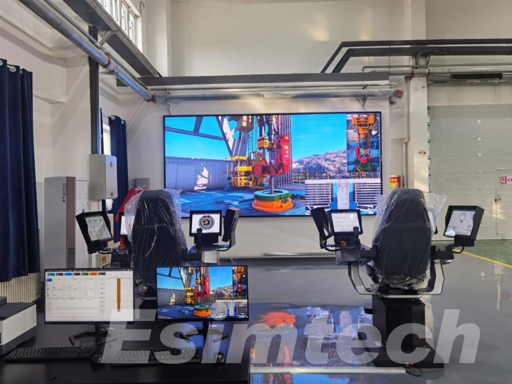
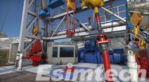
7. Integration of Simulation Technology
This chart outlines the current practices in the industry, where well control simulation technologies are being increasingly integrated into equipment maintenance programs. The degree of sophistication differs significantly, from basic hydraulic modeling software that runs on laptops to fully-scale virtual training systems that simulate whole BOP systems and panels for control.
| Simulation Application | Specific Use in Maintenance | Intended Outcome |
| Virtual BOP Function Testing | Simulates the mechanical and hydraulic response of BOP annular preventers and rams without cycling the actual equipment. | Reduces the wear of seals and components, while also confirming the logic of the control system and timing of hydraulics. |
| Failure Mode Simulation | The simulations simulate the consequences of typical failures, such as leaks in seals and stuck rams. It also models the effects of loss of hydraulic pressure or the an inoperative pilot valve. | Aids maintenance teams to identify the root cause faster and create specific inspection protocols. |
| Maintenance Procedure Training | Technicians can practice difficult tasks such as ram block replacement and annular packer replacement or choke service in a secure virtual space. | Reduces mistakes during maintenance, helps minimize damage to equipment and reduces downtime for repair. |
| Pressure Test Simulation | Recreates high-pressure and low-pressure tests, with expected rate of decay for different sealing conditions. | Allows workers to interpret real pressure test results more precisely and differentiate between normal behavior and real leaks. |
| Hydraulic System Modeling | Simulates the pre-charge level of the accumulator bottle and pump cycling. It also simulates valve response times, as well as the flow of fluid throughout the control system. | Determines when components of the hydraulic system will require maintenance and pinpoints pressure drops or bottlenecks before they can cause field malfunctions. |
| Corrosion and Wear Prediction | Utilizes historical data as well as environmental inputs to simulate the rates of internal corrosion as well as erosion caused by fluids with abrasive properties, as well as fatigue cracks in BOP manifolds and body parts. | Increases inspection intervals, and directs non-destructive testing to most likely areas of failure. |
| Elastomer Aging Simulation | It simulates the degradation of seals and packing machines based on temperature cycles, time and chemical exposure. compression set. | Data-driven replacement schedules that ensure safety and avoid unneeded component changes. |
| Emergency Scenario Drills for Maintenance Teams | Simulates the failure of equipment during an event of well control like the ram not closing properly as well as a choke valve that fails during operation. | Trains maintenance technicians to repair and troubleshoot equipment in simulated emergency situations with no real-world risk. |
| Spare Parts Inventory Modeling | Simulates repair and failure rate times across a number of rigs in order to determine the best levels of inventory for vital components. | It ensures that seals, valves, as well as repair kits are readily available whenever needed, while avoiding excessive cost of inventory. |
| Post-Maintenance Validation Simulation | Performs virtual function and tests the pressure after maintenance is finished, before applying the actual hydraulic pressure or well pressure. | It detects assembly mistakes, incorrect value of torque, improperly aligned seals prior to causing damage, or even create a safety risk that is not visible. |
Avoiding Common Mistakes in Equipment Maintenance during Well Control Operations
This chart outlines the most commonly seen equipment failures that are observed in field operations. Each error is documented in real incidents involving well control or near-misses and the strategies for avoiding them are based on current standards in the industry and expectations from regulatory agencies.
| Common Mistake | Why It Is Dangerous | How to Avoid It |
| Using only visual inspection to determine seals | Elastomers may harden, expand or form tiny cracks that aren’t visible for the untrained eye. A seal that appears perfect could fail completely under pressure. | Replace dynamic seals using a calendar-based schedule, regardless of their appearance. Make use of magnified inspections and durometer tests to determine the importance of static seals. |
| Avoiding low-pressure tests prior to high-pressure tests | A tiny leak could be temporarily sealed through the compression of high pressure but then leaks again as the pressure fluctuates. This can cause a failure that is not obvious. | Always conduct a test of low pressure between 200 and 300 psi at first. If the pressure is stable, move on to high-pressure testing. Record both test results independently. |
| Inattention to small hydraulic leaks on control lines | Slow drips gradually decrease the volume and pressure of the system. In time, pre-charge for the accumulator is reduced as BOPs closing speed decreases without warning. | Consider any leak in the hydraulic system as the first repair priority. Make daily visual inspections of all fittings and control lines. Track leak repairs and log them according to place of repair. |
| Utilizing generic or non-certified replacement components | Valve seals, valves and seals from aftermarket or cartridges might not be able to meet the original tension ratings or chemical resistance or tolerances to dimensions. It is a mystery as to why. | Maintain a strict policy requiring manufacturer-certified or API-specified parts. Keep track of batch numbers and certificates of compliance for each important components. |
| Failure to record the torque values for bolted connections | Over-torqued bolts could break or stretch BOP Flanges. The under-torqued bolts cause unbalanced gasket compression and could create leak pathways under pressure surge. | Utilize torque wrenches that are calibrated. Record each torque value along with the location of the bolt as well as the initials of the technician on your maintenance journal. |
| Only testing from the main control panel | The remote panel or the driller’s may be afflicted by stuck pilot valves or a dead battery or a blockage in the hydraulic system. The primary panel functions but the backup panel is not working whenever it is needed. | Test the function from each control station, including remote, primary and backups in case of emergency on an ongoing schedule. Cycle every ram from each station. |
| Inadvertently ignoring accumulator bottle pre-charge checkpoints | A low nitrogen pre-charge decreases the stored energy. The rams could close slowly or not fully complete their stroke in the event of a real well control incident. | Monitor pre-charge pressure every month and following any system operation that reduces the pressure in the accumulators. Record readings and compare them to the specifications of the manufacturer. |
| Reusing gaskets or O-rings after removal | After being compressed, elastomer is unable to adapt to the irregularities. Seals used in the past tend to leak, sometimes intermittently and irregularly. | Replace the seals as often as connections are damaged or a component is removed. Maintain a supply of the most common O-ring size and gasket dimensions. |
| Storing spare elastomers improperly | The effects of heat, ozone ultraviolet light and humidity speed up aging. Seals placed near motors in direct sunlight or in hot pumps rooms degrade prior to installation. | Keep elastomers stored in sealed bags in an air-conditioned dark, dry, and dark cabinet. Each package should be labeled with the date it was manufactured. Use oldest stock first. |
| Conducting function tests not recording the closing hours | A ram that shuts down slowly is a sign of an insufficient accumulator pressure, hydraulic limitation, or worn-out pump. Without timing information, the gradual decline is not noticed. | Make use of a stopwatch, or an electronic timer to perform each test. Note close times as seconds. Look into any rise above normal values. |
| Refraining maintenance to meet the drilling goals | Each hour that a seal is running over its recommended time increases the chance of failure. Pressure in production is always constant, however well-controlled availability is not an option. | Include maintenance time in your drilling plan. You must conduct a formal review of management-of-change in the event of deferred maintenance with a clear understanding of the the risk. |
| Inability to properly train the crew members in basic maintenance tasks | If the technician who is in charge is absent or not available Untrained employees may complete maintenance in error or miss crucial actions. | Train at least two crew members in every maintenance process. Perform quarterly drills in which each participant demonstrates competence. |
Final Words
The equipment maintenance in the well control process demands discipline and the integration of innovative technologies. When a well goes off and the well is shut, there is no chance to fix a stuck ram or repair a damaged seal. The equipment has to perform immediately and without fail. Through rigorous testing of function and the use of pressure tests, management of elastomers as well as meticulous records operators can transform a heap of valves and steel into a reliable protector against catastrophe.