What Is Stick-Slip in Drilling? Causes, Detection, and Mitigation

Written By: Computer Science Professor
Deeply rooted in the R&D of simulators for the oil and gas industry, committed to bringing safety to every oil worker.
In modern deep well and extended-reach drilling operations, “stick-slip” type intense torsional vibration remains one of the main causes of increased non-productive time (NPT) and failure of downhole tools. When the bit becomes stuck intermittently and suddenly released downhole (i.e., alternating between “stick” and “slip”), it generates destructive torque peaks that can damage PDC cutters and downhole electronics. This paper analyzes the physical dynamics mechanism of the stick-slip phenomenon, outlines practical on-site monitoring methods that can be applied, and demonstrates how advanced drilling simulation technology can assist drilling personnel in building intuition, thereby eliminating torsional vibration before equipment is damaged.
The Downhole Physics of Torsional Destruction
Energy Storage & 3x Surface RPM Spikes
Slippage is one of the most destructive forms of vibration in underground operations, triggered by the nonlinear friction dynamics at the interface between the drill bit and the rock, as well as at the contact points of the drill string. This phenomenon manifests as a violent and self-sustaining energy cycle process:
- Steady-state phase: Due to excessive cutting depth, overly aggressive hydraulic parameters of the drill bit, or excessively high formation friction, the PDC drill bit comes to a complete stop at the bottom of the well (with a rotational speed of 0 RPM). Meanwhile, the surface top drive or the rotary table continues to rotate, causing the drill string that is several miles long to twist and storing a large amount of elastic strain energy.
- Slip phase: When the accumulated torque eventually overcomes the static friction in the well, the stationary drill bit undergoes a violent reverse release (rebound), instantly releasing all the stored kinetic energy and accelerating to 200% to 300% of surface RPM within a few milliseconds.
Process flow:
Surface top rotating (e.g. 100 RPM) -> Drill string twisting (energy storage) -> Drill bit stops rotating at the bottom of the well (steady-state phase) -> Suddenly undergoes a violent rebound, with the rotational speed instantly rising to 300 RPM (slip phase)
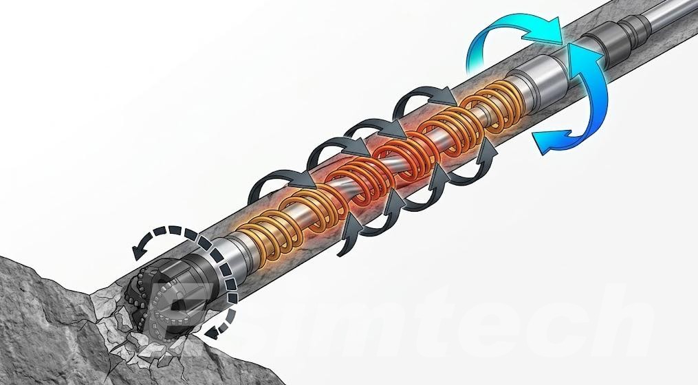
Impact Loading: PDC Shearing & BHA Electronics Failure
The intense and high-frequency impact loads generated during the “slippage” stage can cause severe and rapid mechanical damage to the downhole equipment:
- PDC cutting teeth shear: The micro-impact load can cause the diamond layer at the edge of the PDC cutting teeth to fracture, leading to thermal fatigue, annular spalling, and a rapid decline in mechanical drilling rate (ROP).
- BHA Mechanical Fatigue: The peak of intense torsional acceleration can cause the threads to loosen, the drill string to break, and fatigue cracks to form in the heavy drill collar.
- MWD/LWD failure: Impact loads exceeding 20g from the downhole torsion can damage the sensitive directional gyroscope, acceleration sensor components, and the mud pulse telemetry electronic system.
Real-Time Detection & Parameter Optimization
Surface Indicators: Torque Oscillations and Amperage Spikes
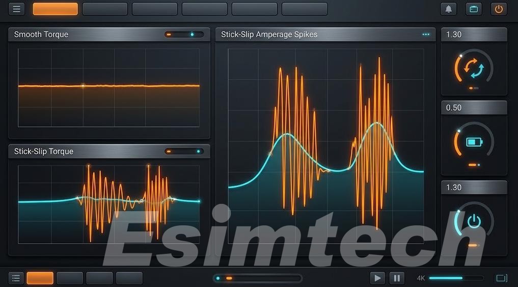
Although the downhole high-frequency storage-type measurement tools can provide accurate vibration telemetry data after the operation is completed, the drilling personnel must learn to identify the subtle signs of the “stick-slip” phenomenon in time before the downhole drilling tool assembly (BHA) suffers catastrophic damage through the control console screen of the driller:
- Top drive current: The appearance of rapid and regular current peaks indicates that the top drive motor is under a huge load due to the severe “stall” encountered by the downhole drill bit.
- Ground torque fluctuation: The occurrence of large sinusoidal torque fluctuations (with an amplitude of ±50% or more from the base drilling torque) reflects that the drill string is undergoing a continuous cyclic “tightening-release” process.
- Mechanical drilling rate (ROP): It is manifested as irregular periodic stagnation followed by sudden jumps; this is caused by intermittent pauses of the PDC bit during the cutting process, followed by re-engagement with the rock surface.
Tuning Beyond “Increase RPM, Decrease WOB”
The classic “increase rotational speed and reduce drilling pressure” strategy in textbooks often fails in deep wells, complex wells, or large-offset wells. Blindly increasing the top drive rotational speed may trigger destructive lateral vibrations or cause the drilling tool assembly to enter the critical resonance range; while significantly reducing the drilling pressure will seriously slow down the mechanical drilling rate and prolong the drilling cycle.
In actual operations, effective parameter adjustments require a clear understanding of the precise operating stable range of the drill string:
- Reduce WOB in small increments: Moderately decrease the initial cutting depth to break the “stuck” cycle of the drill bit, while ensuring that the mechanical drilling rate is not significantly affected.
- Increase RPM selectively (+10 to 15 RPM steps): Gradually increase the rotational speed by 10–15 RPM, using the increased rotational momentum to overcome static friction, while avoiding the lateral resonance frequency of the drilling tool assembly.
- Optimize Mud Rheology & Lubricity: If the friction between the casing and the drill string in the complex large-offset well trajectory is the main cause of torque fluctuations, then the lubrication condition should be improved by adjusting the performance of the drilling fluid or injecting a special lubricant.
Building Driller Instincts via Simulation
When a drilling rig experiences severe stick-slip, the ground torque meter will fluctuate violently, and the top drive motor will emit a sharp screeching sound. Inexperienced drillers are prone to make mistakes, such as over-adjusting the brake pressure or suddenly lifting the drill bit while rotating. This can easily cause impact damage to the downhole drilling assembly (BHA), thermal shock, and even secondary sticking. To eliminate torsional vibration, the driller must remain calm in the noisy and alarm-filled cab and precisely adjust the parameters.
Eliminating Torsional Vibration Using the Esimtech simulator
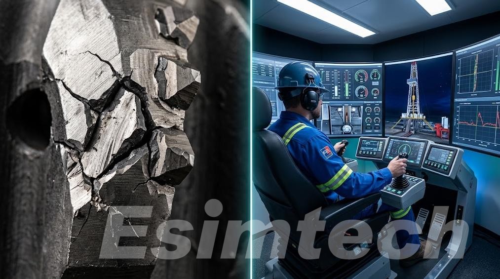
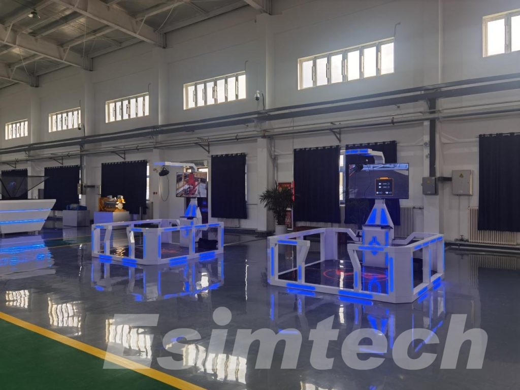
Mastering the suppression of torsional vibration relies on practical experience rather than theoretical explanations. The Esimtech advanced drilling simulator can accurately reproduce the dynamic behavior of the downhole drill string and convert the stick-slip process into real-time feedback:
- Realistic instrument system: Real-time simulation of top drive torque fluctuations, motor current changes, sound alerts, and mechanical brake feedback.
- Dynamic physics engine: Real-time reflection of the impact of parameter adjustments (such as drilling pressure, RPM, or soft torque) on mechanical drilling rate (ROP) and vibration curves.
- Scenario-based training: Helps trainees identify early signs of stick-slip and adjust parameters to stabilize drilling, avoiding severe wear of PDC bits and MWD tools.
Introducing simulation technology into the training system can help drilling contractors protect high-value downhole equipment, reduce non-productive time (NPT), and improve drilling efficiency.