What Is Anti-Collision in Drilling? Methods for Avoiding Wellbore Collision

Written By: Computer Science Professor
Deeply rooted in the R&D of simulators for the oil and gas industry, committed to bringing safety to every oil worker.
With the increasing popularity of clustered well drilling and multi-branch well development in modern oil and gas operations, the underground space has become increasingly crowded and its complexity has reached an unprecedented level. Relying solely on pre-drilling static trajectory models is no longer sufficient to prevent catastrophic wellbore collisions. This article explores a variety of advanced anti-collision technologies and methods – from ISCWSA (International Wellbore Trajectory Measurement Standards Association) uncertainty modeling to real-time measurement correction – and focuses on explaining how high-fidelity simulation can compensate for deviations in the human execution process in high-pressure drilling environments.
Why Standard Anti-Collision Plans Fail in Heavy Pad Drilling
The Limitations of Static Separation Factors
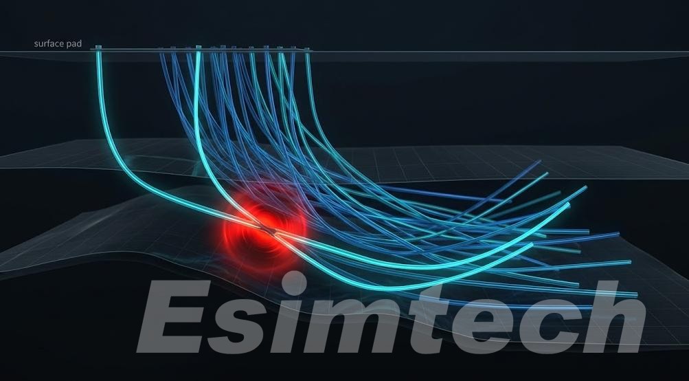
In high-density cluster drilling, multi-branch well development, and offshore platform operation environments, relying solely on the static “well spacing factor” (Separation Factor, abbreviated as SF > 1.5) derived from pre-drilling calculations can lead to a dangerous false sense of security. Pre-drilling models are usually based on idealized wellbore geometries and uniform geological structures; however, various dynamic physical variables are introduced during actual drilling operations – such as BHA sagging, sudden changes in formation dip, torque-induced drill string deflection, and execution errors in sliding operations during directional drilling – all of which can instantly render the initial well spacing calculation results invalid.
When ten or more wellbores are radiating out from the same surface well site, the margin for error becomes extremely small. If dynamic deviations cannot be calculated in real time during drilling, the static safety buffer space reserved during the engineering design stage may completely disappear within a single drilling section.
Ellipsoid of Uncertainty Accumulation: How Survey Drift Erases Your Safety Margin
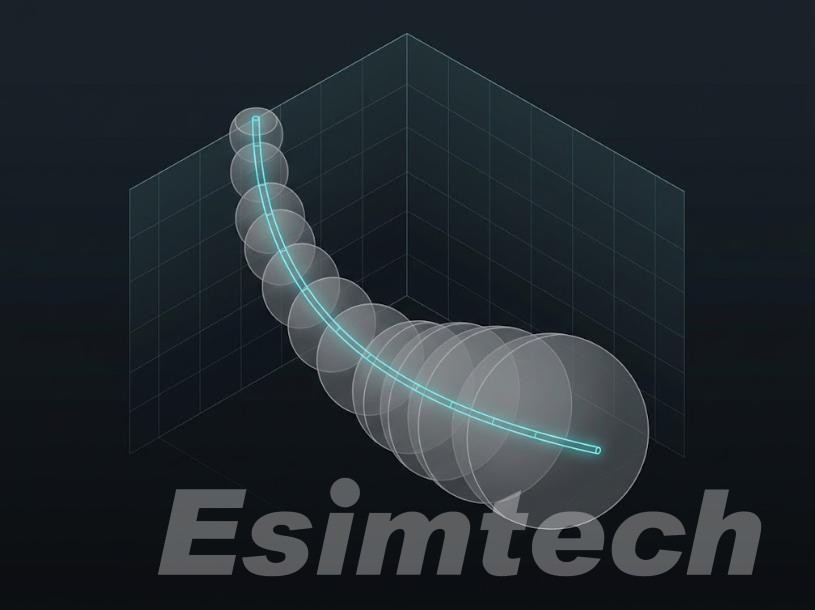
The uncertainty of the wellbore position is not a constant value but expands exponentially with the increase in measurement depth (MD). The “Ellipsoid of Uncertainty” (EOU) represents the three-dimensional confidence region around any measurement point on the wellbore trajectory. As the drilling operation progresses deeper:
- The magnetic interference generated by the adjacent casing string and iron-rich formations causes distortion in the azimuth readings of the measurement while drilling (MWD).
- Gyro drift, sensor installation deviation, and thermal expansion effects introduce systematic positional errors.
- The microscopic curvature (micro-tortuosity) and doglegs of the wellbore can cause unmeasured lateral displacements.
If the error model is not continuously updated, the “Ellipsoid of Uncertainty” of adjacent wellbores may inadvertently exceed critical safety spacing boundaries; yet, the coordinates calculated based on the original MWD measurements still appear “absolutely safe” on paper.
Hard Protocols When Separation Rules Are Breached
Deciphering the ISCWSA Error Models in High-Risk Zones
Modern wellbore collision prevention operations require the active and automatic integration of the error model of the ISCWSA. Field engineers must continuously calculate the three-dimensional net distance ratio (based on the center distance of the wellbore) between the target well and all adjacent wells to constantly assess the actual probabilistic safety boundary.
In areas with extremely small wellbore spacing (such as in surface drilling operations with extremely high well cluster density), the original measurement data is no longer sufficient to meet the requirements. At this time, it is necessary to combine high-frequency “Field Reference” (IFR) technology or “While Drilling Gyro Measurement” (GWD) technology to correct the real-time MWD data. Reducing the uncertainty radius of the reference well and adjacent wells is the only reliable way to maintain a mathematically valid safety net distance range.
Emergency Avoidance SOP: Nudge, Sidetrack, or Shut-In?
When real-time measurement monitoring reveals that the “Separation Factor” (SF) inevitably drops below the critical operational threshold (SF < 1.0), no discussion or speculation is allowed regarding safety regulations. The on-site operation team must strictly follow the following four-step response procedure:
- Immediately stop drilling: Immediately halt rotary drilling and circulation operations, secure the drill string, and verify the integrity of the measurement data to rule out the possibility of remote sensing failures.
- Adjust the trajectory direction: Immediately adjust the tool face angle of the directional drilling assembly (BHA) to move the wellbore trajectory away from the “Uncertainty Enclosure Boundary” (EOU boundary) of the adjacent well.
- Perform mechanical sidetracking: If the predicted trajectory inevitably overlaps with the safety envelope area of the adjacent well, then cement plugs must be pumped in and a controlled mechanical sidetracking operation must be carried out.
- Shut down the adjacent well: If there is a risk of physical contact or formation fluid connection, the adjacent well must be immediately shut down to isolate the wellbore reservoir pressure and prevent the escalation of the blowout situation.
The Human Element: Bridging Decision Delays Under Pressure
Why Software Warnings Don’t Prevent Collisions (and People Do)
The collision prevention software can process complex 3D spatial models and the ISCWSA algorithm within a few milliseconds. However, in high-pressure operation sites, the software is unable to make critical execution decisions. Recent incidents and collision accidents in the development of dense well groups mainly resulted from delays in human decision-making: directional drilling engineers and drilling supervisors, due to the urgency of production progress, doubted the alerts issued by the automated software, or misjudged the changes in the directional trend during conventional sliding drilling. During data disputes, even a hesitation of three to five meters in the drilling depth could lead to a catastrophic wellbore collision accident, causing millions of dollars in losses.
Simulating High-Proximity Scenarios in Full-Scale Drilling Simulators
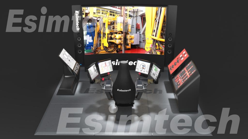
To eliminate decision delays, it is necessary to go beyond the traditional classroom lectures and slide presentations. The high-fidelity drilling simulator can fill this crucial gap, allowing directional drilling engineers, drilling engineers, and drilling site supervisors to be immersed in a realistic and high-pressure “wellbore proximity” scenario.
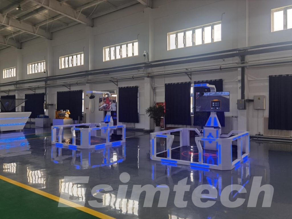
Using Esimtech Drilling Simulation Systems, oilfield operators and operator training centers can model complex pad geometries, inject realistic MWD sensor drift, and replicate high-stress SF breach alarms. Crew members actively practice interpreting dynamic 3D traveling cylinder plots, evaluating spider graphs, and executing emergency nudging or sidetracking protocols under true-to-life operational stress. By transforming theoretical clearance rules into practical muscle memory, field personnel build the rapid, decisive judgment required to keep high-density drilling operations safe and productive.